Logan Manual Lathe: Difference between revisions
(remove an old threading snippet) |
|||
| (10 intermediate revisions by 3 users not shown) | |||
| Line 1: | Line 1: | ||
[[Category:Tools]][[Category:Lathes -- Metal]] | [[Category:Tools]][[Category:Lathes -- Metal]] | ||
Link to:[[:Category:Machine Shop | Machine Shop Main Page]] | Link to:[[:Category:Machine Shop | Machine Shop Main Page]] | ||
{{Warning|text=You must be tool tested to use the Logan lathe. These instructions are for reference and are not a replacement for training, instruction, or tool testing.}}{{EyeWarning}} | |||
{{EyeWarning}} | |||
{{ToolBox | {{ToolBox | ||
| Line 13: | Line 12: | ||
|serial = | |serial = | ||
|manufacturer_specs = | |manufacturer_specs = | ||
|manual = [https://drive.google.com/file/d/ | |manual = [https://drive.google.com/file/d/186Nb1m3Di_qlNRdSHWwWzY5saOKa-L_0/view?usp=drive_link Instructions] | ||
|location = Machine Shop | |location = Machine Shop | ||
|rubric = N/A | |rubric = N/A | ||
| Line 21: | Line 20: | ||
|tool_categories = [[:Category:Lathes -- Metal | See the Lathes category for notes on using all lathes]] | |tool_categories = [[:Category:Lathes -- Metal | See the Lathes category for notes on using all lathes]] | ||
}} | }} | ||
Link to: [https://drive.google.com/file/d/16gzoJdF_DkQVSmnvT53TnAoI4R_8fatx/view?usp=drive_link Parts List] | |||
Link to: [https://drive.google.com/file/d/186Nb1m3Di_qlNRdSHWwWzY5saOKa-L_0/view?usp=drive_link Instructions] | |||
==Safety== | ==Safety== | ||
| Line 26: | Line 29: | ||
Link to: [https://wiki.artisansasylum.com/wiki/Category:Lathes_--_Metal#Safety Safety notes on the Metal-cutting lathes category page] | Link to: [https://wiki.artisansasylum.com/wiki/Category:Lathes_--_Metal#Safety Safety notes on the Metal-cutting lathes category page] | ||
== | Do not attempt to use this machine unless you have been properly trained and tool-tested. | ||
== Changing the spindle speed == | |||
The Logan lathe has mechanical variable speed adjustment. This has a continuous range instead of discrete belt positions, but for the adjustment to work properly, the lathe must be running when you adjust the speed. With the lathe powered on, turn the handwheel on the stand until the speed dial shows the desired speed. The speed dial has two speed ranges; the lower speed range shows the spindle speed in back gear, and the higher speed range shows the spindle speed in high gear. | |||
=== Back Gear === | |||
Like the [[South Bend Manual Lathe|South Bend]], the Logan has a back gear to allow low speed, high torque spindle rotation. To put the Logan into back gear, pull the spindle clutch collar away from the headstock to disengage the clutch dogs. Then, lift the back gear lever up and pull it towards you until the lever clicks into place. Reverse these operations to go back into high gear; Lift the back gear lever and push it into the machine. Next, re-engage the spindle clutch collar by pushing it towards the headstock, making sure to align the clutch dogs.<gallery> | |||
File:Logan clutch collar engaged.jpeg|Logan clutch collar engaged. Note how the clutch dogs mesh with the spindle dogs in this position. | |||
File:Logan clutch collar disengaged.jpeg|Logan clutch collar disengaged from the spindle. Note how the clutch dogs do not mesh with the spindle dogs in this position. | |||
</gallery> | |||
[[File:Logan headstock controlls.jpeg|alt=Overview of Logan headstock controls|thumb|Overview of the Logan lathe headstock controls. To engage back gear, lift and pull the back gear lever (a) towards you and disengage the clutch collar. Disengage back gear by lifting and pushing the back gear lever and re-engaging the clutch collar. Power cross and carriage feed can be enabled with the power feed selector (b), and feed rate (or thread pitch if you're cutting threads) can be adjusted with the feedrate/thread pitch adjustment levers (c).]] | |||
Back gear creates additional mechanical, gear-meshing noise. Again, this noise is normal, but grinding or rubbing noises are not, so stop the lathe if you hear something unusual. | |||
You can also lock the spindle by engaging back gear without disengaging the spindle clutch collar. This is useful for installing and removing chucks, but it will cause belts to rub and quickly wear if you try to operate the lathe in this condition. | |||
== Power Feed == | |||
The Logan has both power carriage feed and power cross feed. The keyway in the leadscrew powers this power feeding, so the leadscrew must be enabled to use power feed. With the lathe powered off, enable the power feed by moving the power feed lever out of the neutral position and into the appropriate direction. Note that turning and facing operations typically require different power feed lever settings. | |||
[[File:Logan apron controls.jpeg|alt=Overview of the apron controls on the Logan lathe|thumb|Overview of the apron controls on the Logan Lathe. Pick between power carriage feed, neutral, and power cross feed with the power feed selector lever (a). Lift up the the power feed clutch lever (b) to activate power feed, and push it down to deactivate it. The half nut lever (c) and thread dial (d) are pictured here, but are not used for power feeding.]] | |||
With the lathe still powered off, move the power feed lever on the apron to the appropriate setting. Disengage the power feed by pushing the clutch lever on the apron down before turning on the lathe. Engage power feed by lifting the clutch lever up, and confirm that the correct feed knob is turning in the correct direction. | |||
Two levers control the speed of the power feed. The leftmost position of these levers is the fastest feed speed, while the rightmost position is the slowest. Position E has a good range of feed rates, and this is typically the right setting for the first lever. | |||
== Installing and Removing Chucks == | |||
The Logan has a keyed, tapered spindle. The taper of the spindle registers against an internal taper inside the back of the chucks, and the key in the spindle fits into a keyway in the back of the chucks. A threaded locking collar on the spindle threads into the back of the chuck, and tightening this collar pulls the tapered surfaces against each other. Unlike the threaded spindle on the South Bend, the Logan’s concentric accuracy comes from the fit of these tapered surfaces against each other, and the keyed spindle allows the Logan spindle to run in both directions without loosening the chuck. | |||
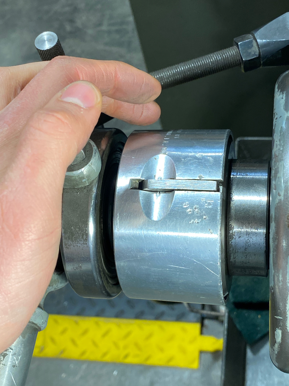
[[File:Logan chuck removal.jpeg|alt=Logan lathe chuck removal process|thumb|Logan lathe chuck removal process. Use the chuck collar wrench to loosen the locking collar. If the collar is tight, use a mallet to tap the wrench until the collar is loose enough to turn by hand. Note the wooden block supporting the bottom of the chuck. It's a good idea to clean any loose chips and debris out of the spindle and chuck when switching the chucks around.]] | |||
The Logan’s chucks are large and heavy, so use a wooden cradle on top of the ways to support the weight of the chuck and protect the ways from damage. To remove a chuck, use the collar wrench and mallet to turn the locking collar. Push the wrench away from the apron to unthread the collar from the chuck. After removing the chuck, clean chips from the spindle nose and the inside taper of the chuck. Install a chuck by performing these operations in reverse. First, ensure that both the spindle and the chuck taper are clear of chips and debris. Use a wooden cradle to align the chuck with the spindle, paying attention to the location of the spindle key. Screw the locking collar onto the threads of the chuck, and use the collar wrench to snug up the collar. | |||
=== Installing and Removing the Collet Closer === | |||
The Logan has a collet closer to enable use of 5C collets. The collet closer has a threaded tube that fits through the spindle bore and threads into the back of the 5C collets. The back end of the collet closer has a lever that pulls the collet into a tapered 5c collet adapter and collet chuck to tighten the collets around the work. It also has an adjustment mechanism to set the tension of the collet. | |||
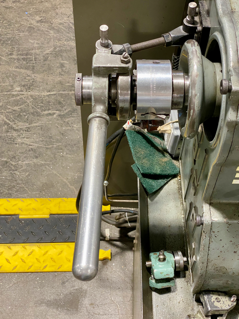
[[File:Logan collet closer components.jpeg|alt=Overview of the Logan 5C collet closer assembly|thumb|Overview of the components of the Logan's 5C collet closer, arranged as if they were installed in the lathe. The collet closer itself (a) goes through the back of the spindle into the spindle nose. The collet chuck (b, pictured backwards here) threads onto the spindle nose like the other Logan chucks. The tapered 5C collet adapter (c) fits inside the spindle nose inside taper. The 5C collet itself (d) goes into the 5C collet adapter, and the threaded end of the collet closer threads over the collet's external threads. The blue shaded region shows where the headstock would be relative to these collet closer components.]] | |||
Start by removing any chuck installed on the spindle and clearing any chips present. Next, install the collet chuck onto the spindle, tightening the locking collar to secure the collet chuck onto the spindle. Insert the 5C collet adapter into the collet chuck and firmly tap the adapter to seat it into the collet chuck taper. This taper holds the collet adapter securely inside the collet chuck, and you will not be able to remove it without removing the collet chuck from the spindle. | |||
Next, insert the collet closer through the back of the spindle. Select an appropriately sized collet to hold your work. The work should fit into the collet easily, but there should not be any slop. Insert the collet into the front of the spindle, ensuring the keyway in the collet aligns with the key inside of the 5C collet adapter. Tighten the knurled tension adjustment knob to thread the collet threads into the collet closer. With the work inside the collet, adjust the tension until the collet closer lever closes with firm – but not excessive – force. Lower the locking tab into the closest locking groove to lock in this collet closer tension setting.<gallery> | |||
File:Logan collet closer headstock.jpeg|The headstock end of the Logan collet closer. Note that the adjustment locking tab is sticking up, so the collet closer tension can be adjusted. | |||
File:Logan collet closer adjustment.jpeg|Detail view of the collet closer adjustment tab. When the tab is sticking up like this, the tension can be adjusted. | |||
File:Logan collet closer adjustment locked.jpeg|Detail of the collet closer adjustment locked into place. The adjustment tab is down, and the collet closer tension setting is locked into place. Raise the locking tab to make adjustments to the collet closer tension. | |||
</gallery>Perform these operations in reverse to remove the collet closer. Clean chips and debris out of the spindle, chuck, and adapters before putting them away. | |||
[[File:Logan collet closer at home.jpeg|thumb|When it's not in use, the Logan's collet closer lives on a mount behind the lathe.]] | |||
Latest revision as of 22:38, 12 April 2024
Link to: Machine Shop Main Page
| You must be tool tested to use the Logan lathe. These instructions are for reference and are not a replacement for training, instruction, or tool testing. | |
|---|---|
| Eye protection required! | ||
|---|---|---|
| Logan Lathe | |
|---|---|
| General Info | |
| Make | Logan |
| Model | |
| Serial | |
| Specs | |
| Manual | Instructions |
| Asylum Info | |
| Location | Machine Shop |
| Rubric | N/A |
| Training | |
| Testing | Tool testing |
| Restrictions | red |

See the Lathes category for notes on using all lathes
Link to: Parts List
Link to: Instructions
Safety
Link to: Safety notes on the Metal-cutting lathes category page
Do not attempt to use this machine unless you have been properly trained and tool-tested.
Changing the spindle speed
The Logan lathe has mechanical variable speed adjustment. This has a continuous range instead of discrete belt positions, but for the adjustment to work properly, the lathe must be running when you adjust the speed. With the lathe powered on, turn the handwheel on the stand until the speed dial shows the desired speed. The speed dial has two speed ranges; the lower speed range shows the spindle speed in back gear, and the higher speed range shows the spindle speed in high gear.
Back Gear
Like the South Bend, the Logan has a back gear to allow low speed, high torque spindle rotation. To put the Logan into back gear, pull the spindle clutch collar away from the headstock to disengage the clutch dogs. Then, lift the back gear lever up and pull it towards you until the lever clicks into place. Reverse these operations to go back into high gear; Lift the back gear lever and push it into the machine. Next, re-engage the spindle clutch collar by pushing it towards the headstock, making sure to align the clutch dogs.
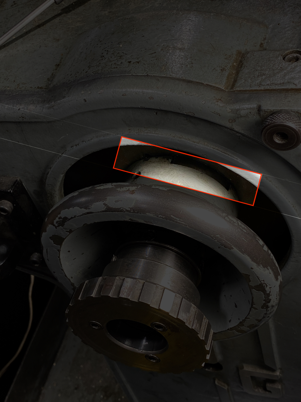
Logan clutch collar engaged. Note how the clutch dogs mesh with the spindle dogs in this position.
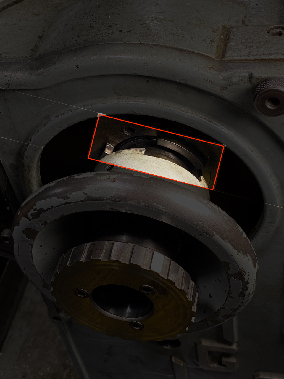
Logan clutch collar disengaged from the spindle. Note how the clutch dogs do not mesh with the spindle dogs in this position.


Back gear creates additional mechanical, gear-meshing noise. Again, this noise is normal, but grinding or rubbing noises are not, so stop the lathe if you hear something unusual.
You can also lock the spindle by engaging back gear without disengaging the spindle clutch collar. This is useful for installing and removing chucks, but it will cause belts to rub and quickly wear if you try to operate the lathe in this condition.
Power Feed
The Logan has both power carriage feed and power cross feed. The keyway in the leadscrew powers this power feeding, so the leadscrew must be enabled to use power feed. With the lathe powered off, enable the power feed by moving the power feed lever out of the neutral position and into the appropriate direction. Note that turning and facing operations typically require different power feed lever settings.

With the lathe still powered off, move the power feed lever on the apron to the appropriate setting. Disengage the power feed by pushing the clutch lever on the apron down before turning on the lathe. Engage power feed by lifting the clutch lever up, and confirm that the correct feed knob is turning in the correct direction.
Two levers control the speed of the power feed. The leftmost position of these levers is the fastest feed speed, while the rightmost position is the slowest. Position E has a good range of feed rates, and this is typically the right setting for the first lever.
Installing and Removing Chucks
The Logan has a keyed, tapered spindle. The taper of the spindle registers against an internal taper inside the back of the chucks, and the key in the spindle fits into a keyway in the back of the chucks. A threaded locking collar on the spindle threads into the back of the chuck, and tightening this collar pulls the tapered surfaces against each other. Unlike the threaded spindle on the South Bend, the Logan’s concentric accuracy comes from the fit of these tapered surfaces against each other, and the keyed spindle allows the Logan spindle to run in both directions without loosening the chuck.

The Logan’s chucks are large and heavy, so use a wooden cradle on top of the ways to support the weight of the chuck and protect the ways from damage. To remove a chuck, use the collar wrench and mallet to turn the locking collar. Push the wrench away from the apron to unthread the collar from the chuck. After removing the chuck, clean chips from the spindle nose and the inside taper of the chuck. Install a chuck by performing these operations in reverse. First, ensure that both the spindle and the chuck taper are clear of chips and debris. Use a wooden cradle to align the chuck with the spindle, paying attention to the location of the spindle key. Screw the locking collar onto the threads of the chuck, and use the collar wrench to snug up the collar.
Installing and Removing the Collet Closer
The Logan has a collet closer to enable use of 5C collets. The collet closer has a threaded tube that fits through the spindle bore and threads into the back of the 5C collets. The back end of the collet closer has a lever that pulls the collet into a tapered 5c collet adapter and collet chuck to tighten the collets around the work. It also has an adjustment mechanism to set the tension of the collet.

Start by removing any chuck installed on the spindle and clearing any chips present. Next, install the collet chuck onto the spindle, tightening the locking collar to secure the collet chuck onto the spindle. Insert the 5C collet adapter into the collet chuck and firmly tap the adapter to seat it into the collet chuck taper. This taper holds the collet adapter securely inside the collet chuck, and you will not be able to remove it without removing the collet chuck from the spindle.
Next, insert the collet closer through the back of the spindle. Select an appropriately sized collet to hold your work. The work should fit into the collet easily, but there should not be any slop. Insert the collet into the front of the spindle, ensuring the keyway in the collet aligns with the key inside of the 5C collet adapter. Tighten the knurled tension adjustment knob to thread the collet threads into the collet closer. With the work inside the collet, adjust the tension until the collet closer lever closes with firm – but not excessive – force. Lower the locking tab into the closest locking groove to lock in this collet closer tension setting.
The headstock end of the Logan collet closer. Note that the adjustment locking tab is sticking up, so the collet closer tension can be adjusted.
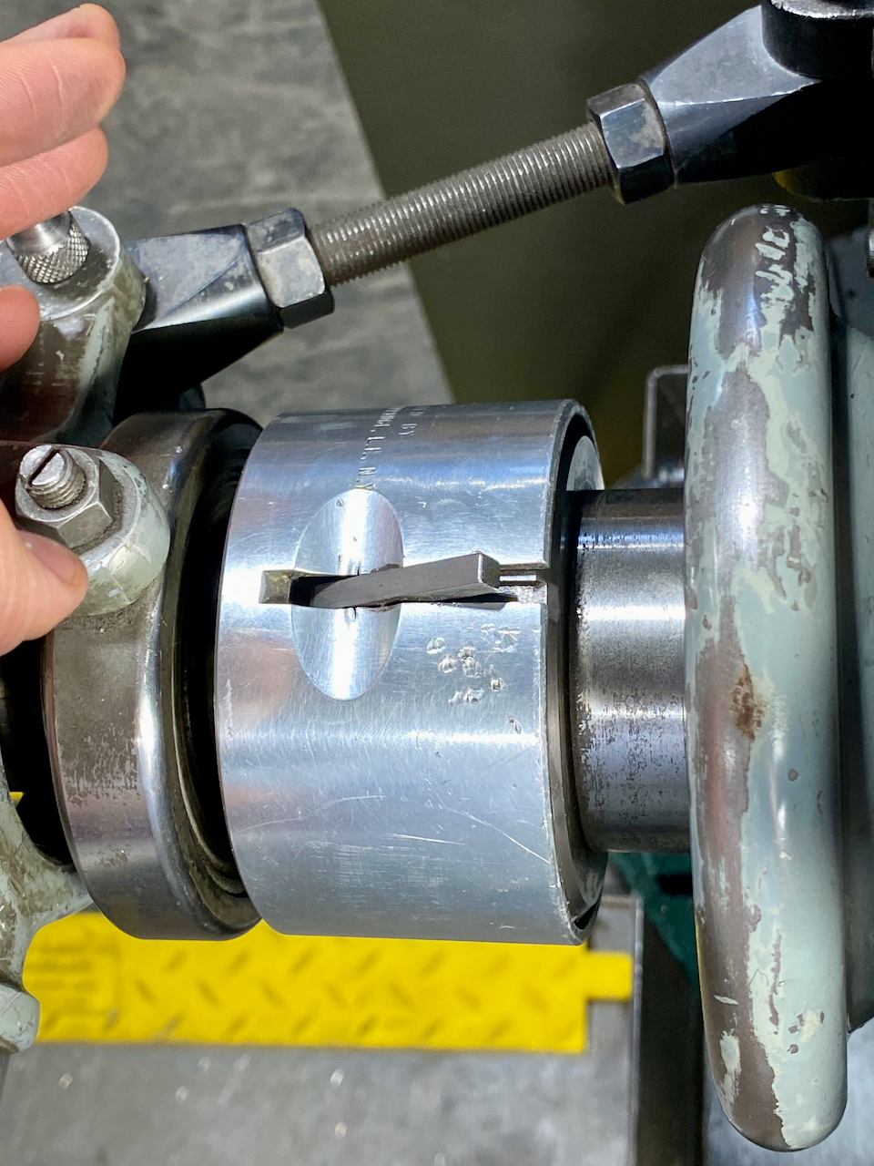
Detail view of the collet closer adjustment tab. When the tab is sticking up like this, the tension can be adjusted.
Detail of the collet closer adjustment locked into place. The adjustment tab is down, and the collet closer tension setting is locked into place. Raise the locking tab to make adjustments to the collet closer tension.


Perform these operations in reverse to remove the collet closer. Clean chips and debris out of the spindle, chuck, and adapters before putting them away.

