Intro to the metal lathe: Difference between revisions
(add power turning) |
(describe lathe axes) |
||
| (5 intermediate revisions by the same user not shown) | |||
| Line 3: | Line 3: | ||
=== Overview === | === Overview === | ||
[[File:Parts of a lathe2 labeled.png|alt=Components of a metal lathe|thumb|Major components of a metal lathe. The lathe holds the work in a chuck affixed to the ''headstock'' or between centers (as shown above). The ''carriage'' moves the tool parallel to the spindle bore, the ''cross slide'' moves the tool perpendicular to the spindle bore, and the ''compound slide'' (sometimes called the ''top slide'') can move at an adjustable compound angle. Several controls for moving the carriage and slides are located on the ''apron''.]] | [[File:Parts of a lathe2 labeled.png|alt=Components of a metal lathe|thumb|Major components of a metal lathe. The lathe holds the work in a chuck affixed to the ''headstock'' or between centers (as shown above). The ''carriage'' moves the tool parallel to the spindle bore, the ''cross slide'' moves the tool perpendicular to the spindle bore, and the ''compound slide'' (sometimes called the ''top slide'') can move at an adjustable compound angle. Several controls for moving the carriage and slides are located on the ''apron''.|344x344px]] | ||
The lathe holds material securely and spins it | The lathe holds material securely and spins it around the axis of the spindle bore. As the material spins, operators can move a cutting tool against the work parallel to the spindle bore with the ''carriage'', which travels along the ''ways'', the prismatic rails on the bed of the lathe. Users can also move the tool perpendicular to the work with the ''cross slide'', and at a compound angle with the ''compound'' (often referred to as the ''top slide''). Users can adjust the depth of cut by adjusting these controls in unison, allowing them to make round, concentric features with precise dimensions. | ||
==== Concentricity: the Superpower of a Metal Lathe ==== | ==== Concentricity: the Superpower of a Metal Lathe ==== | ||
| Line 20: | Line 20: | ||
One lathe specific hazard is the hazard of an unattended chuck key flying out of the chuck when the lathe turns on. Pay attention to where you pick up the chuck key and where you put it down after adjusting the chuck; unless you're actively adjusting the chuck, the key should be outside of the chuck and away from the headstock. | One lathe specific hazard is the hazard of an unattended chuck key flying out of the chuck when the lathe turns on. Pay attention to where you pick up the chuck key and where you put it down after adjusting the chuck; unless you're actively adjusting the chuck, the key should be outside of the chuck and away from the headstock. | ||
Several common free-machining materials contain lead to improve machinability. These materials are nice to work with, but the presence of lead makes them somewhat hazardous. You should wash your hands after using the lathe, especially if you're working with these kinds of materials. Common lead-containing materials include 12L14 steel, a free machining steel alloy, and C360 brass, | It's possible for parts of the lathe to run into each other in unintended, chaotic ways. Chuck jaws can protrude from the edge or the face of the chuck, making it possible for parts of the carriage to crash violently with the spinning chuck jaws. It's good idea to manually spin the chuck to make sure that there's enough clearance between the different components of the lathe to avoid a crash, especially when working close to the chuck. | ||
Several common free-machining materials contain lead to improve machinability. These materials are nice to work with, but the presence of lead makes them somewhat hazardous. You should wash your hands after using the lathe, especially if you're working with these kinds of materials. Common lead-containing materials include 12L14 steel, a free machining steel alloy, and C360 brass, one of the most common brass alloys. | |||
Grinding lathe tool bits creates metal and abrasive dust. This dust is a respiratory hazard, so you should use the dust extractor connected to the grinders and wear a respirator or mask when grinding. | Grinding lathe tool bits creates metal and abrasive dust. This dust is a respiratory hazard, so you should use the dust extractor connected to the grinders and wear a respirator or mask when grinding. | ||
| Line 45: | Line 47: | ||
=== Anatomy of a Single Point Cutting Tool === | === Anatomy of a Single Point Cutting Tool === | ||
Most lathe cutting tools are ''single point cutting tools''; they remove material from the stock at a single point instead of plowing away material along a long cutting edge (these are often called ''form tools''). Single point cutting tools have several surfaces that contribute to their cutting behavior | Most lathe cutting tools are ''single point cutting tools''; they remove material from the stock at a single point instead of plowing away material along a long cutting edge (these are often called ''form tools''). Single point cutting tools have several surfaces that contribute to their cutting behavior. [https://www.youtube.com/watch?v=__A2xtLF0AU ''This Old Tony'' has an excellent video on YouTube] describing the different features of a single point cutting tool and how to create them. | ||
==== Front and Side | ==== Front and Side Clearance ==== | ||
Imagine a square cutting bit with a square front face held square to the work. Turning down an outside diameter (an ''OD'') with this setup would create a new, smaller OD and a perpendicular shoulder where the new OD transitions back to the original OD. Because the tool is square in all dimensions, the left side of the tool would rub against this shoulder, and the front of the tool underneath the cutting edge would rub against the new OD. Tool rubbing creates friction and chatter, which leads to poor cutting behavior. We can fix this by grinding away material from the front of the tool and the left side of the tool. | Imagine a square cutting bit with a square front face held square to the work. Turning down an outside diameter (an ''OD'') with this setup would create a new, smaller OD and a perpendicular shoulder where the new OD transitions back to the original OD. Because the tool is square in all dimensions, the left side of the tool would rub against this shoulder, and the front of the tool underneath the cutting edge would rub against the new OD. Tool rubbing creates friction and chatter, which leads to poor cutting behavior. We can fix this by grinding away material from the front of the tool and the left side of the tool.<gallery> | ||
File:Square lathe tool front view.png|A square lathe tool and stock, viewed from the tailstock. Te squared-off front surface of this lathe tool (highlighted in blue) will rub against the outside diameter it just cut (highlighted in red). | |||
File:Square lathe tool top view.png|A square lathe tool and stock, viewed from the top. Te squared-off front surface of this lathe tool (highlighted in blue) will rub against the outside diameter it just cut (highlighted in red). | |||
</gallery>[view of the front of the tool highlighting clearance surfaces] | |||
==== Nose Radius ==== | ==== Nose Radius ==== | ||
We've given clearance to the tool, but the newly ground surfaces of the tool come together at a sharp, beveled point. This tool is sharp, but it's brittle. It's like a really sharp pencil; it has a nice point, but it breaks quickly and is not durable. We can fix this by grinding a nose radius on this corner. I recommend grinding this by hand with a bench stone, since a grinder can remove too much material too quickly. | We've given clearance to the tool, but the newly ground surfaces of the tool come together at a sharp, beveled point. This tool is sharp, but it's brittle. It's like a really sharp pencil; it has a nice point, but it breaks quickly and is not durable. We can fix this by grinding a nose radius on this corner. I recommend grinding this by hand with a bench stone, since a grinder can remove too much material too quickly. Smaller nose radii make for sharper tools that require less power from the machine, but they're not as durable and they leave a rougher surface. Larger nose radii make tools more durable and lead to smoother finishes, but they require more power and aren't as suitable for shallower cuts. | ||
[show the nose radius before and after] | [show the nose radius before and after] | ||
| Line 70: | Line 73: | ||
Install a tool into one of the quick change tool holders and adjust the angle of the toolpost to make sure the tool is cutting on its nose radius and not rubbing against the stock. [image of what that looks like]. With the toolpost lever loose, adjust the thumbscrew on the tool holder to raise and lower the tool; we'll use this screw to get the tool centered to the work. | Install a tool into one of the quick change tool holders and adjust the angle of the toolpost to make sure the tool is cutting on its nose radius and not rubbing against the stock. [image of what that looks like]. With the toolpost lever loose, adjust the thumbscrew on the tool holder to raise and lower the tool; we'll use this screw to get the tool centered to the work. | ||
There are several ways to center the tool. One method is to pinch a small ruler against the side of the stock with the tip of the tool. If the tool is too high, the ruler will be tipping | There are several ways to center the tool. One method is to pinch a small ruler against the side of the stock with the tip of the tool. If the tool is too high, the top of the ruler will be tipping away from the operator. If the tool is too low, the top of the ruler will be tipping towards the operator. When the tool is on center, the ruler will be vertical. [picture of too high, too low, on center.] | ||
The best method for proving that the tool is centered is to take a facing cut. If the tool is centered, there will not be a nub in the center of the stock after facing. If the tool is too low, there will be a top-hat shaped nub. If the tool is too high, there will be a pointed nub, and you'll notice more resistance against the handwheel as the tool tries to bulldoze through the material instead of cutting it. | The best method for proving that the tool is centered is to take a facing cut. If the tool is centered, there will not be a nub in the center of the stock after facing. If the tool is too low, there will be a top-hat shaped nub. If the tool is too high, there will be a pointed nub, and you'll notice more resistance against the handwheel as the tool tries to bulldoze through the material instead of cutting it. | ||
=== Picking a Speed === | === Picking a Speed === | ||
We often express lathe cutting speeds in ''surface feet per minute'' (SFM) or ''inches per minute'' (IPM). We can use a target SFM value and material diameter to determine an RPM for our operation.<blockquote>RPM = SFM (feet/minute) * (12 inches/foot) * (1/pi) | We often express lathe cutting speeds in ''surface feet per minute'' (SFM) or ''inches per minute'' (IPM). We can use a target SFM value and material diameter to determine an RPM for our operation.<blockquote>RPM = SFM (feet/minute) * (12 inches/foot) * (1/pi) / work diameter (inches)</blockquote>Substituting 4 for (12 inches/foot)) * (1/pi), this gets us<blockquote>RPM = SFM (feet/minute) * 4 /work diameter (inches)</blockquote>300 feet/minute for delrin is a reasonable cutting speed, so 900 RPM is a good place to start for 1" delrin. | ||
Consult a feeds/speeds chart or an app like FSwizard for determining cutting speeds for other materials, but bear in mind that these feeds and speeds are geared towards production machinists trying to get their work done as quickly as possible. Time is money in these settings, so these speeds tend to be pretty aggressive. Err on the side of lower speeds while you're learning to use a new machine or work with a new material. | Consult a feeds/speeds chart or an app like FSwizard for determining cutting speeds for other materials, but bear in mind that these feeds and speeds are geared towards production machinists trying to get their work done as quickly as possible. Time is money in these settings, so these speeds tend to be pretty aggressive. Production machines tend to be beefier, more rigid, and more powerful, and they can handle these faster and deeper cuts. Err on the side of lower speeds while you're learning to use a new machine or work with a new material. | ||
=== Check for Clearance === | === Check for Clearance === | ||
Before making any cuts with the lathe, make sure the spindle can spin without hitting anything like the tool or the toolpost. Clearance issues are more likely to come up with turning cuts than with facing cuts, so figure out where the deepest turning cut will be. Move the carriage to this position and manually spin the chuck to make sure the chuck jaws won't crash into anything. Install a hard stop onto the ways to prevent the carriage from moving too close to the chuck and crashing. | Before making any cuts with the lathe, make sure the spindle can spin without hitting anything like the tool or the toolpost. Clearance issues are more likely to come up with turning cuts than with facing cuts, so figure out where the deepest turning cut will be. Move the carriage to this position and manually spin the chuck to make sure the chuck jaws won't crash into anything. Install a hard stop onto the ways to prevent the carriage from moving too close to the chuck and crashing. | ||
=== Understanding Lathe Coordinates === | |||
The lathe's carriage moves along the Z axis. The position of the tool along the Z axis gets more negative as the carriage moves towards the headstock and more positive as it moves away from the headstock. | |||
The cross slide moves along the X axis. The position of the tool along the X axis gets more negative as the cross slide moves towards the operator and more positive as it moves away from the operator. | |||
The Y axis measures the height of the tool in the toolpost. Once we get the tool height centered, we don't typically worry about movement on the Y axis. | |||
[[File:Lathe coordinate system.jpg|alt=lathe coordinate system|thumb|420x420px|The X and Z axes of a lathe. The carriage moves along the Z axis, which gets increasingly positive as the carriage moves away from the headstock. The cross slide moves along the X axis, which gets increasingly positive as the cross slide moves away from the operator side.]] | |||
=== Take a Facing Cut === | === Take a Facing Cut === | ||
| Line 89: | Line 100: | ||
==== Facing with Power Feed ==== | ==== Facing with Power Feed ==== | ||
Engage the power feed lever at the headstock and pick an appropriate feed rate (0.005"/revolution is a good place to start). Then set the power feed selector lever on the apron to power cross feed. With the tool clear of the stock, power on the lathe and engage the power feed clutch. The tool will move slowly, so it's easier to see the handwheel movement. Disengage the power feed clutch, move the tool close to the stock, and take a facing cut with the power feed. Compare the surface finish from manual feed with the surface finish from power feed. | Engage the power feed lever at the headstock and pick an appropriate feed rate (0.005"/revolution is a good place to start). Then set the power feed selector lever on the apron to power cross feed. With the tool clear of the stock, power on the lathe and engage the power feed clutch. The tool will move slowly, so it's easier to see the handwheel movement. Disengage the power feed clutch, move the tool close to the stock, and take a facing cut with the power feed. Compare the surface finish from manual feed with the surface finish from power feed. | ||
==== Measuring Facing Cuts ==== | |||
The carriage movements of the South Bend and Logan lathes are not calibrated to a precise measurement dial, so you need to use a dial indicator to measure the amount of carriage movement. Both lathes have indicator holders that clamp onto the ways and allow measuring the carriage travel. | |||
[photo of indicator clamp on the ways] | |||
=== Take a Turning Cut. === | === Take a Turning Cut. === | ||
Move the cross slide back so the tool is clear of the stock. Power on the lathe and move the tool close to the surface of the stock | Move the cross slide back so the tool is clear of the stock. Power on the lathe and move the tool close to the surface of the stock. Wind the carriage away from the headstock, then move the cross slide closer to the stock, then move the carriage towards the headstock slightly. If you see chips, set the cross slide dial to zero and continue winding the carriage towards the headstock. If you don't see chips, wind the carriage away from the stock, wind the cross slide in a little more, and repeat until you start to see chips. | ||
Take a few turning cuts. Try removing different amounts of stock on each turning cut, and try to get a sense of how much resistance you get with different depths of cut. | Take a few turning cuts. Try removing different amounts of stock on each turning cut, and try to get a sense of how much resistance you get with different depths of cut. | ||
| Line 97: | Line 113: | ||
==== Turning with Power Feed. ==== | ==== Turning with Power Feed. ==== | ||
This is just like facing with power feed, but with the added risk of the tool crashing into the headstock. Be vigilant about disengaging the clutch before the carriage hits the hard stop. Again, repeat this a few times to get a sense of the power feed controls. | This is just like facing with power feed, but with the added risk of the tool crashing into the headstock. Be vigilant about disengaging the clutch before the carriage hits the hard stop. Again, repeat this a few times to get a sense of the power feed controls. | ||
==== Measuring Turning Cuts ==== | |||
The cross slide dial helps us much stock we remove on turning cuts. Cross slide dials come in direct read and indirect read flavors. Both the South Bend and the Logan lathes have ''direct read'' cross slide dials; the reading on the cross slide dials tell us the amount of ''diameter'' reduction. If you move the cross slide from 0.000" to 0.020" and take a cut, the cut will make the work's diameter 0.020" smaller. | |||
Other lathes have ''indirect read'' cross slide dials. These dials measure the amount of ''radius'' reduction. Moving the cross slide from 0.000" to 0.020" removes 0.020" from the radius of the work, which translates to a 0.040" reduction of diameter. Direct read and indirect read dials work equally well, but you have to know which one you're using to produce accurate work on the lathe. | |||
[picture of cross slide dials] [picture of dial indicator on south bend] [picture of indirect read dial indicator on acer] | |||
=== Drill a Hole with the Tailstock === | |||
When aligned properly, the tailstock allows you to drill a perfectly centered hole in your work. Remove any tooling in the tailstock by retracting the quill all the way. Clean debris out from the inside surface of the quill, extend the quill about an inch, and firmly insert a drill chuck. Make sure that the tapered surfaces are locked together. | |||
We'll use a ''center drill'' or a ''spot drill'' to start a pilot hole. These drill bits are stubby and rigid, which helps us drill an accurate hole in the center of the work. Center drills have a stepped point that matches the taper angle of a lathe center. Lathe centers are useful for certain operations, but most drill bits have a different point angle, so be careful not to drill too deep with a center drill when drilling a pilot hole. Spot drills are closer to common drill point angles, so they don't require the same care. | |||
[picture of center drill] [picture of spot drill] | |||
Insert a center drill or a spot drill into the drill chuck in the tailstock and move the tailstock close to the face of the work. Tighten the tailstock, turn on the lathe, and use a pecking motion to drill into the face of the work. Replace the center drill or spot drill in the chuck with a slightly larger twist drill and repeat the positioning, tightening, and pecking operations to enlarge the hole. The machine shop has several different kinds of cutting lubricant for different materials. We use blue lids for aluminum cutting lube, red lids for steel cutting lube, and white lids for stainless steel cutting lube. Some materials like brass and delrin don't need cutting lube. | |||
==== Measuring Drilling Operations. ==== | |||
Measuring the depth of a drilled hole can be tricky because of the pointed tips of drill bits. Is a 0.25" diameter, 1" deep hole measuring from the deepest part of the hole cut by the tip, is it measuring from the deepest part of the whole with the full 1" diameter? Good drawings will usually call this out, and there are formulas to convert between depth-of-tip and depth-of-full-diameter measurements. In many cases this difference isn't super important, but it's worth thinking about when you need to drill a blind hole in a part. | |||
The quill has markings on it to allow you to measure how much you extend it. For holes that don't need super precision, I find it easier to mark the desired depth of the hole with tape on the drill bit. For more precise holes, we have an adapter that allows you to measure the travel of the quill with a dial indicator. | |||
[picture of point in drilled hole] [picture of blue tape on drill bit] [picture of dial indicator adapter setup] | |||
=== Parting Off Work === | |||
You can cut off work from the lathe using a ''parting tool'', a narrow, blade-like form tool. This operation is called ''parting'' or ''parting off'', and it can be tricky and dangerous. If you have a large part to cut off or the stock is an especially tough material, it is often safer to remove the work from the lathe and cut it with the bandsaw. | |||
Parting leaves a much better surface finish than the bandsaw, and parting often allows us to quickly create a lot of identical parts that require minimal dressing up afterwards. Parting safely requires careful setup, slow speeds and feeds, and lots of lubrication.. Check the parting tool for sharpness before using it, and hone it if needed. | |||
Parting requires more precise tool setup than most other lathe operations. The tool must be perfectly square to the spindle axis and the tool must be perfectly on center. Often, you can use a machined face of your work or the flat face of the chuck as a reference surface to square up the parting tool. | |||
A common mistake with parting is to forget to account for the width of the parting tool when parting off work, leading to shorter-than-expected parts. One way to zero the Z axis of the parting tool is to place a straightedge on the face of the work and to move the carriage to the right until the left side of the straightedge and right side of the parting tool make contact. | |||
Refer to [https://www.youtube.com/watch?v=5LtYzjR1JuM this video on the details of using a parting tool] for a good overview of parting. | |||
Latest revision as of 15:00, 17 September 2024
Metal lathes are versatile tools that we use to make precise round parts. These kinds of precise round parts show up in everything from small consumer goods to heavy industrial machinery, and they make smooth and efficient movement possible. Metal lathes achieve this through accurate linear movement and rigidity, which allows us to make parts with exacting dimensions and concentric features. In this class, we'll learn how to safely operate the manual metal lathes, produce some simple parts, and explore some of the many ways we can fabricate parts with a manual metal lathe.
How Does a Metal Lathe Work?
Overview

The lathe holds material securely and spins it around the axis of the spindle bore. As the material spins, operators can move a cutting tool against the work parallel to the spindle bore with the carriage, which travels along the ways, the prismatic rails on the bed of the lathe. Users can also move the tool perpendicular to the work with the cross slide, and at a compound angle with the compound (often referred to as the top slide). Users can adjust the depth of cut by adjusting these controls in unison, allowing them to make round, concentric features with precise dimensions.
Concentricity: the Superpower of a Metal Lathe
The spindle of the lathe spins in an accurate circle, so every cut will produce a feature concentric with the spindle axis. The lathe has precisely machined axes, so the carriage will move parallel to the spindle axis, and the cross slide will move perpendicular to the spindle axis. Turning cuts with the carriage will produce precise cylindrical features, while facing cuts with the cross slide will produce flat surfaces perpendicular to the spindle axis.

The circles in this bullseye share the same center, so they're concentric.

The circles in this bullseye do not share the same centers, so they're eccentric.


Rigidity: the Corollary to the Metal Lathe Superpower
The ways of the lathe are parallel to the spindle bore, and the cross slide movement is perpendicular to the spindle bore. Ideally, all cuts would follow these parallel and perpendicular constraints, but the intense cutting forces cause all of the components -- the work, the tools, and even the lathe itself -- to flex to some degree. We try to minimize this by building the lathe out of sturdy materials; the South Bend 9A, the smallest lathe in the machine shop, weighs over a half a ton. We also reduce the amount of flex by limiting both tool and material stick-out and controlling the aggressiveness of our cuts.
Metal Lathe Safety
The biggest safety hazard with the metal lathe is getting snagged by the spinning chuck or the work it's holding. Do not wear rings, watches, jewelry, gloves, or loose clothing that could be caught in the chuck. Tie back long hair before using the lathe, and keep your hands clear of the headstock while the lathe is spinning.
One lathe specific hazard is the hazard of an unattended chuck key flying out of the chuck when the lathe turns on. Pay attention to where you pick up the chuck key and where you put it down after adjusting the chuck; unless you're actively adjusting the chuck, the key should be outside of the chuck and away from the headstock.
It's possible for parts of the lathe to run into each other in unintended, chaotic ways. Chuck jaws can protrude from the edge or the face of the chuck, making it possible for parts of the carriage to crash violently with the spinning chuck jaws. It's good idea to manually spin the chuck to make sure that there's enough clearance between the different components of the lathe to avoid a crash, especially when working close to the chuck.
Several common free-machining materials contain lead to improve machinability. These materials are nice to work with, but the presence of lead makes them somewhat hazardous. You should wash your hands after using the lathe, especially if you're working with these kinds of materials. Common lead-containing materials include 12L14 steel, a free machining steel alloy, and C360 brass, one of the most common brass alloys.
Grinding lathe tool bits creates metal and abrasive dust. This dust is a respiratory hazard, so you should use the dust extractor connected to the grinders and wear a respirator or mask when grinding.
General shop safety rules apply too. You must wear safety glasses and closed toed shoes in the machine shop, regardless of whether you're using any machinery. Review the safety guidelines on the metal lathe overview page for more guidance.
Kicking the Tires on the Lathes
Refer to the dedicated pages for the South Bend and Logan lathes for detailed instructions.
Moving the Carriage and Slides
Use the handwheels on the apron to move the carriage towards and away from the headstock. Note the relationship between carriage movement direction and handwheel movement direction. Repeat this movement for the cross slide and the compound slide.
Adjusting the Spindle Speed
Move the carriage away from the chuck and the headstock. Determine a spindle speed and turn on the lathe to that speed. On the South Bend, you pick the spindle speed by moving the belts to a specific position. On the Logan, you change the spindle speed by turning the speed adjustment handle with the lathe powered on.
Try several different speeds on the lathes. What sounds does the lathe make at a high speed? What about a lower speed? Do you notice the mechanical, gear-meshing noises when running the lathes in back gear?
Engaging Power Feed
Both the South Bend and the Logan have power carriage and power cross feed. Power feed moves the tool at a steady, consistent speed, and an appropriate feed rate can produce an excellent surface finish. We'll get to cutting with power feed eventually, but for now, enable power feed with the controls on the headstock, then power on the lathe. Listen for the extra mechanical, gear-meshing noises and watch for the leadscrew movement.
First Cuts on the Lathe
We're going to install a tool on to the lathe, then take some facing cuts, then take some turning cuts.
Anatomy of a Single Point Cutting Tool
Most lathe cutting tools are single point cutting tools; they remove material from the stock at a single point instead of plowing away material along a long cutting edge (these are often called form tools). Single point cutting tools have several surfaces that contribute to their cutting behavior. This Old Tony has an excellent video on YouTube describing the different features of a single point cutting tool and how to create them.
Front and Side Clearance
Imagine a square cutting bit with a square front face held square to the work. Turning down an outside diameter (an OD) with this setup would create a new, smaller OD and a perpendicular shoulder where the new OD transitions back to the original OD. Because the tool is square in all dimensions, the left side of the tool would rub against this shoulder, and the front of the tool underneath the cutting edge would rub against the new OD. Tool rubbing creates friction and chatter, which leads to poor cutting behavior. We can fix this by grinding away material from the front of the tool and the left side of the tool.
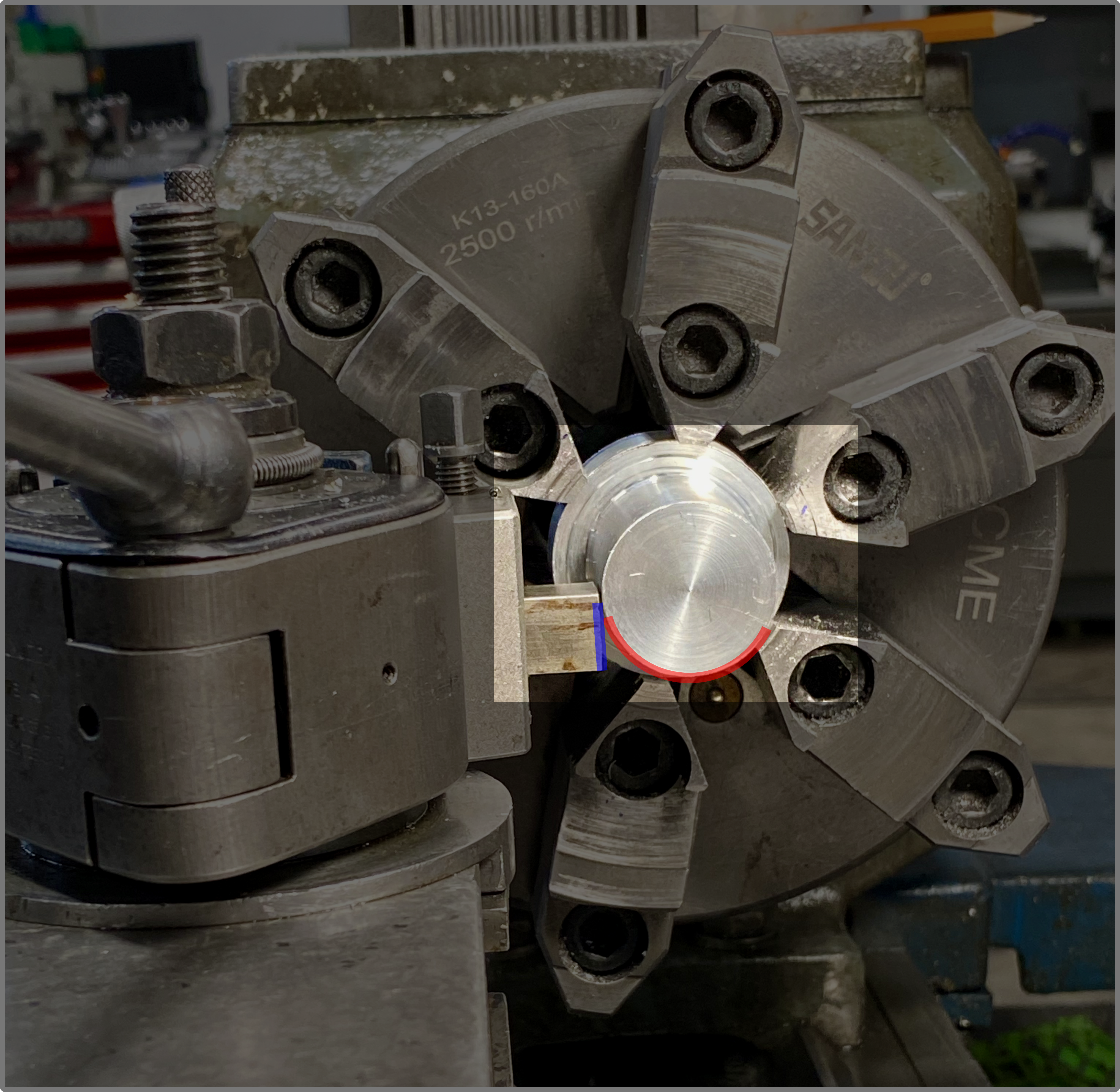
A square lathe tool and stock, viewed from the tailstock. Te squared-off front surface of this lathe tool (highlighted in blue) will rub against the outside diameter it just cut (highlighted in red).
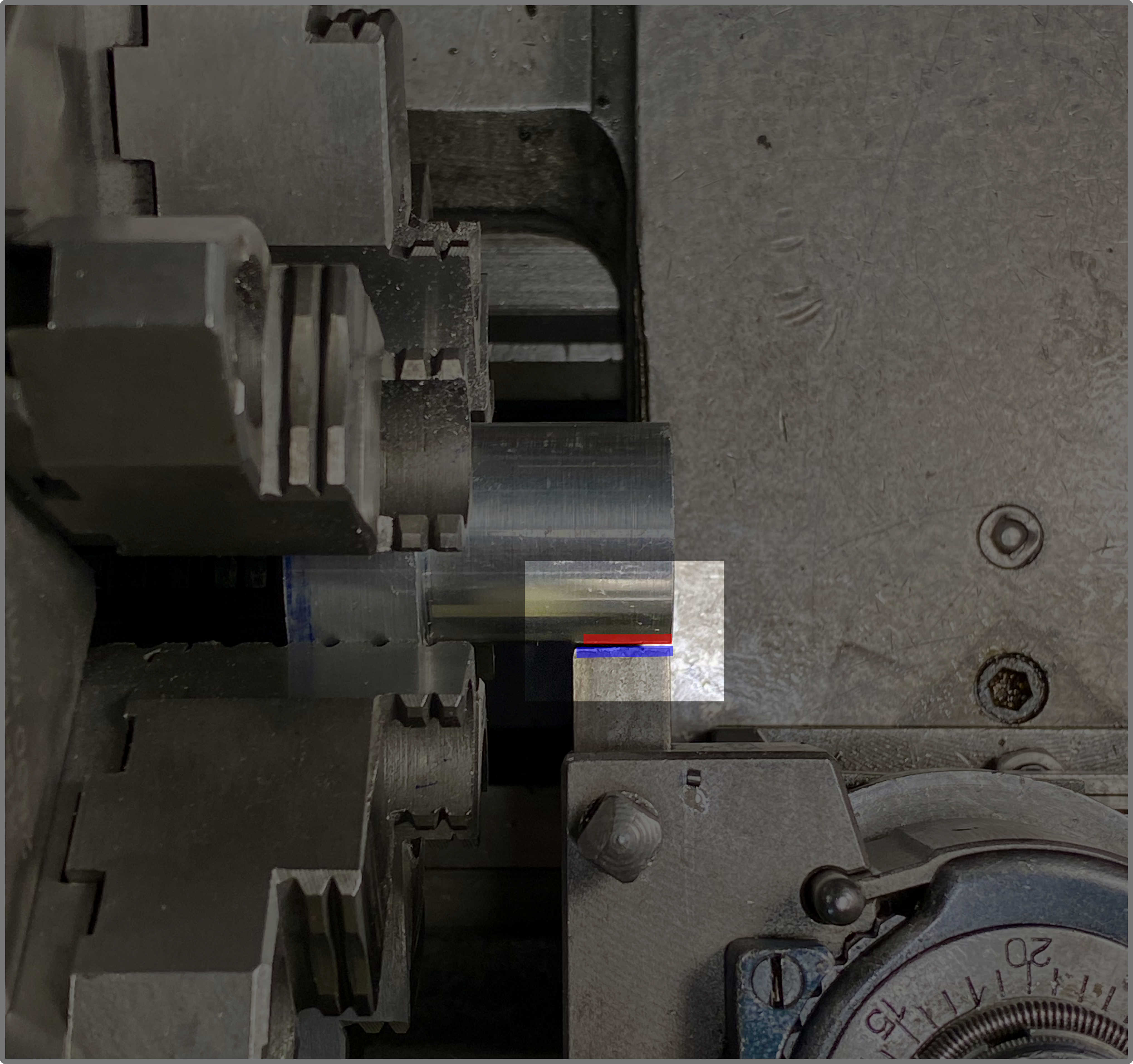
A square lathe tool and stock, viewed from the top. Te squared-off front surface of this lathe tool (highlighted in blue) will rub against the outside diameter it just cut (highlighted in red).


[view of the front of the tool highlighting clearance surfaces]
Nose Radius
We've given clearance to the tool, but the newly ground surfaces of the tool come together at a sharp, beveled point. This tool is sharp, but it's brittle. It's like a really sharp pencil; it has a nice point, but it breaks quickly and is not durable. We can fix this by grinding a nose radius on this corner. I recommend grinding this by hand with a bench stone, since a grinder can remove too much material too quickly. Smaller nose radii make for sharper tools that require less power from the machine, but they're not as durable and they leave a rougher surface. Larger nose radii make tools more durable and lead to smoother finishes, but they require more power and aren't as suitable for shallower cuts.
[show the nose radius before and after]
Rake Angle
Nose radius measures how sharp the front of the tool is, while rake angle measures how sharp the top of the tool is. The tool we just ground has a flat, horizontal top, perpendicular to the front of the tool. This tool has zero rake, and it works well for brass and plastics, but other materials -- typically aluminum and steel -- cut better with positive rake tools. These tools have a <90º angle between the front of the tool and the top of the tool, and we can grind this tool by grinding the top of the tool.
[image of front of tool with zero and with positive rake]
Getting Ready to Cut
Holding the Stock
Loosen the three jaw chuck, then place a piece of 1" delrin bar stock in the chuck with about an inch of stickout. Tighten the chuck jaws and remember to remove the key from the chuck.
Installing the Tool
Install a tool into one of the quick change tool holders and adjust the angle of the toolpost to make sure the tool is cutting on its nose radius and not rubbing against the stock. [image of what that looks like]. With the toolpost lever loose, adjust the thumbscrew on the tool holder to raise and lower the tool; we'll use this screw to get the tool centered to the work.
There are several ways to center the tool. One method is to pinch a small ruler against the side of the stock with the tip of the tool. If the tool is too high, the top of the ruler will be tipping away from the operator. If the tool is too low, the top of the ruler will be tipping towards the operator. When the tool is on center, the ruler will be vertical. [picture of too high, too low, on center.]
The best method for proving that the tool is centered is to take a facing cut. If the tool is centered, there will not be a nub in the center of the stock after facing. If the tool is too low, there will be a top-hat shaped nub. If the tool is too high, there will be a pointed nub, and you'll notice more resistance against the handwheel as the tool tries to bulldoze through the material instead of cutting it.
Picking a Speed
We often express lathe cutting speeds in surface feet per minute (SFM) or inches per minute (IPM). We can use a target SFM value and material diameter to determine an RPM for our operation.
RPM = SFM (feet/minute) * (12 inches/foot) * (1/pi) / work diameter (inches)
Substituting 4 for (12 inches/foot)) * (1/pi), this gets us
RPM = SFM (feet/minute) * 4 /work diameter (inches)
300 feet/minute for delrin is a reasonable cutting speed, so 900 RPM is a good place to start for 1" delrin.
Consult a feeds/speeds chart or an app like FSwizard for determining cutting speeds for other materials, but bear in mind that these feeds and speeds are geared towards production machinists trying to get their work done as quickly as possible. Time is money in these settings, so these speeds tend to be pretty aggressive. Production machines tend to be beefier, more rigid, and more powerful, and they can handle these faster and deeper cuts. Err on the side of lower speeds while you're learning to use a new machine or work with a new material.
Check for Clearance
Before making any cuts with the lathe, make sure the spindle can spin without hitting anything like the tool or the toolpost. Clearance issues are more likely to come up with turning cuts than with facing cuts, so figure out where the deepest turning cut will be. Move the carriage to this position and manually spin the chuck to make sure the chuck jaws won't crash into anything. Install a hard stop onto the ways to prevent the carriage from moving too close to the chuck and crashing.
Understanding Lathe Coordinates
The lathe's carriage moves along the Z axis. The position of the tool along the Z axis gets more negative as the carriage moves towards the headstock and more positive as it moves away from the headstock.
The cross slide moves along the X axis. The position of the tool along the X axis gets more negative as the cross slide moves towards the operator and more positive as it moves away from the operator.
The Y axis measures the height of the tool in the toolpost. Once we get the tool height centered, we don't typically worry about movement on the Y axis.

Take a Facing Cut
Power on the lathe and move the tool towards the face of the material. Use the cross slide to move the tool inside the cross section of the stock, and move the carriage towards the stock until you see chips form. Use the cross slide handwheel to wind the tool away from the stock, then move the carriage a small amount towards the headstock, and then wind the cross slide in towards the center of the work. Continue turning the handwheel until you reach the center of the work, then wind the carriage away from the stock. Power off the lathe and take a look at the newly flat surface you've created!
Repeat this a few times. Try taking shallower cuts and deeper cuts. Try winding the cross slide out instead of the carriage when you've reached the center of the stock. Try adjusting the tool height to be a little too high or a little too low.
Facing with Power Feed
Engage the power feed lever at the headstock and pick an appropriate feed rate (0.005"/revolution is a good place to start). Then set the power feed selector lever on the apron to power cross feed. With the tool clear of the stock, power on the lathe and engage the power feed clutch. The tool will move slowly, so it's easier to see the handwheel movement. Disengage the power feed clutch, move the tool close to the stock, and take a facing cut with the power feed. Compare the surface finish from manual feed with the surface finish from power feed.
Measuring Facing Cuts
The carriage movements of the South Bend and Logan lathes are not calibrated to a precise measurement dial, so you need to use a dial indicator to measure the amount of carriage movement. Both lathes have indicator holders that clamp onto the ways and allow measuring the carriage travel.
[photo of indicator clamp on the ways]
Take a Turning Cut.
Move the cross slide back so the tool is clear of the stock. Power on the lathe and move the tool close to the surface of the stock. Wind the carriage away from the headstock, then move the cross slide closer to the stock, then move the carriage towards the headstock slightly. If you see chips, set the cross slide dial to zero and continue winding the carriage towards the headstock. If you don't see chips, wind the carriage away from the stock, wind the cross slide in a little more, and repeat until you start to see chips.
Take a few turning cuts. Try removing different amounts of stock on each turning cut, and try to get a sense of how much resistance you get with different depths of cut.
Turning with Power Feed.
This is just like facing with power feed, but with the added risk of the tool crashing into the headstock. Be vigilant about disengaging the clutch before the carriage hits the hard stop. Again, repeat this a few times to get a sense of the power feed controls.
Measuring Turning Cuts
The cross slide dial helps us much stock we remove on turning cuts. Cross slide dials come in direct read and indirect read flavors. Both the South Bend and the Logan lathes have direct read cross slide dials; the reading on the cross slide dials tell us the amount of diameter reduction. If you move the cross slide from 0.000" to 0.020" and take a cut, the cut will make the work's diameter 0.020" smaller.
Other lathes have indirect read cross slide dials. These dials measure the amount of radius reduction. Moving the cross slide from 0.000" to 0.020" removes 0.020" from the radius of the work, which translates to a 0.040" reduction of diameter. Direct read and indirect read dials work equally well, but you have to know which one you're using to produce accurate work on the lathe.
[picture of cross slide dials] [picture of dial indicator on south bend] [picture of indirect read dial indicator on acer]
Drill a Hole with the Tailstock
When aligned properly, the tailstock allows you to drill a perfectly centered hole in your work. Remove any tooling in the tailstock by retracting the quill all the way. Clean debris out from the inside surface of the quill, extend the quill about an inch, and firmly insert a drill chuck. Make sure that the tapered surfaces are locked together.
We'll use a center drill or a spot drill to start a pilot hole. These drill bits are stubby and rigid, which helps us drill an accurate hole in the center of the work. Center drills have a stepped point that matches the taper angle of a lathe center. Lathe centers are useful for certain operations, but most drill bits have a different point angle, so be careful not to drill too deep with a center drill when drilling a pilot hole. Spot drills are closer to common drill point angles, so they don't require the same care.
[picture of center drill] [picture of spot drill]
Insert a center drill or a spot drill into the drill chuck in the tailstock and move the tailstock close to the face of the work. Tighten the tailstock, turn on the lathe, and use a pecking motion to drill into the face of the work. Replace the center drill or spot drill in the chuck with a slightly larger twist drill and repeat the positioning, tightening, and pecking operations to enlarge the hole. The machine shop has several different kinds of cutting lubricant for different materials. We use blue lids for aluminum cutting lube, red lids for steel cutting lube, and white lids for stainless steel cutting lube. Some materials like brass and delrin don't need cutting lube.
Measuring Drilling Operations.
Measuring the depth of a drilled hole can be tricky because of the pointed tips of drill bits. Is a 0.25" diameter, 1" deep hole measuring from the deepest part of the hole cut by the tip, is it measuring from the deepest part of the whole with the full 1" diameter? Good drawings will usually call this out, and there are formulas to convert between depth-of-tip and depth-of-full-diameter measurements. In many cases this difference isn't super important, but it's worth thinking about when you need to drill a blind hole in a part.
The quill has markings on it to allow you to measure how much you extend it. For holes that don't need super precision, I find it easier to mark the desired depth of the hole with tape on the drill bit. For more precise holes, we have an adapter that allows you to measure the travel of the quill with a dial indicator.
[picture of point in drilled hole] [picture of blue tape on drill bit] [picture of dial indicator adapter setup]
Parting Off Work
You can cut off work from the lathe using a parting tool, a narrow, blade-like form tool. This operation is called parting or parting off, and it can be tricky and dangerous. If you have a large part to cut off or the stock is an especially tough material, it is often safer to remove the work from the lathe and cut it with the bandsaw.
Parting leaves a much better surface finish than the bandsaw, and parting often allows us to quickly create a lot of identical parts that require minimal dressing up afterwards. Parting safely requires careful setup, slow speeds and feeds, and lots of lubrication.. Check the parting tool for sharpness before using it, and hone it if needed.
Parting requires more precise tool setup than most other lathe operations. The tool must be perfectly square to the spindle axis and the tool must be perfectly on center. Often, you can use a machined face of your work or the flat face of the chuck as a reference surface to square up the parting tool.
A common mistake with parting is to forget to account for the width of the parting tool when parting off work, leading to shorter-than-expected parts. One way to zero the Z axis of the parting tool is to place a straightedge on the face of the work and to move the carriage to the right until the left side of the straightedge and right side of the parting tool make contact.
Refer to this video on the details of using a parting tool for a good overview of parting.
