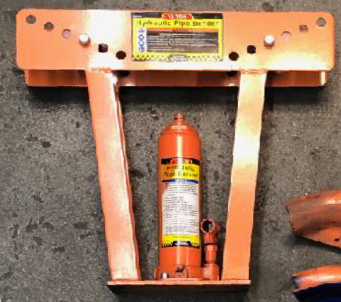
Hydraulic Pipe Bender: Difference between revisions
No edit summary |
No edit summary |
||
| Line 76: | Line 76: | ||
{| class="infobox" cellspacing="5" style="width: 22em; text-align: left; font-size: 100%; line-height: 1.5em;" | {| class="infobox" cellspacing="5" style="width: 22em; text-align: left; font-size: 100%; line-height: 1.5em;" | ||
! colspan="2" class="infobox-image" | [[File:Hydraulic_pipe_bender_inserting_the_die.png| | ! colspan="2" class="infobox-image" | [[File:Hydraulic_pipe_bender_inserting_the_die.png|300px|inserting the die ]] | ||
|- | |- | ||
| colspan="2" | Inserting the die into the hydraulic pipe bender | | colspan="2" | Inserting the die into the hydraulic pipe bender | ||
| Line 97: | Line 97: | ||
{| class="infobox" cellspacing="5" style="width: 22em; text-align: left; font-size: 100%; line-height: 1.5em;" | {| class="infobox" cellspacing="5" style="width: 22em; text-align: left; font-size: 100%; line-height: 1.5em;" | ||
! colspan="2" class="infobox-image" | [[File:Hydraulic_pipe_bender_bending.png| | ! colspan="2" class="infobox-image" | [[File:Hydraulic_pipe_bender_bending.png|375px|bender bending ]] | ||
|- | |- | ||
| colspan="2" | Bending the pipe | | colspan="2" | Bending the pipe | ||
| Line 114: | Line 114: | ||
{| class="infobox" cellspacing="5" style="width: 22em; text-align: left; font-size: 100%; line-height: 1.5em;" | {| class="infobox" cellspacing="5" style="width: 22em; text-align: left; font-size: 100%; line-height: 1.5em;" | ||
! colspan="2" class="infobox-image" | [[File:Hydraulic_pipe_bender_labeled.png| | ! colspan="2" class="infobox-image" | [[File:Hydraulic_pipe_bender_labeled.png|600px|bender labeled]] | ||
|- | |- | ||
| colspan="2" | The hydraulic pipe bender with parts labeled | | colspan="2" | The hydraulic pipe bender with parts labeled | ||
|- | |- | ||
|} | |} | ||
Revision as of 12:16, 7 February 2024
| 12-Ton Hydraulic Pipe Bender | |
|---|---|
| General Info | |
| Make | Central Machinery |
| Model | 12-Ton |
| Serial | Unknown |
| Specs | n/a |
| Manual | Manual |
| Asylum Info | |
| Location | Metal Shop |
| Rubric | n/a |
| Training | Tool classes |
| Testing | Tool testing, or [[:Category:Metal Shop#Tool Testing
Night|come to the shop on Tool Testing Night]] |
| Restrictions | green |
Use for:
- Schedule 40 or 80 malleable steel pipe, sized to match the bender’s dies.
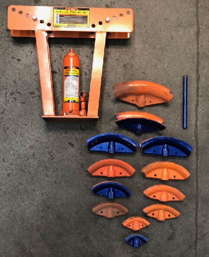
- Six dies match the capacity of the 12 ton hydraulic jack: 1/2”, 3/4”, 1”, 1-1/4”, 1-1/2”, 2”
- 3” and 2-1/2” dies are for the 16 ton version of this machine, not owned by the metal shop.
- Bend pipe up to 90 degrees
Do Not Use for:
- Painted pipe or pipe with debris on it. (Avoid uneven and excessive stress on the dies, and prevent flying debris.)
- Welded or excessively work hardened metals.
Hazard Analysis
- Metal can slip or snap while bending, and flakes of rust, mill scale, or paint can become airborne.
- Debris will interfere with the rollers and dies.
- Pinched fingers, skin. Keep hand away from ram, pipe, and rollers during use.
- Cuts / Scrapes from sharp cut edges of workpiece.
- Cuts / Scrapes / bruises if care is not taken to prevent metal stock from slipping during the bending process.
| Eye protection required! | ||
|---|---|---|
| |
|---|---|
| Pipe Bender with Dies. |
Operation Notes
- Only use pipe that fits the bending die exactly, or significant deformation will occur.
- Keep rollers clean. Obstructions on the rollers create an uneven surface, excess stress, and possible breakage.
- The manufacture’s manual DOES NOT recommend use of pipe bender while on its side. “The hydraulic ram may leak or function improperly.”
- Be aware that 2-1/2” and 3” Bending Dies belong to the Harbor Freight 16 Ton Hydraulic Pipe bender and are not rated for the 12 Ton version of this tool.
- Use only on free standing pipe. Do not use on pipe that is part of an assembly or attached to a structure.
Basic Operation Instructions
1. Perform a safety check. This tool involves signifiant force — do not use damaged equipment. Discontinue use if abnormal noise or vibration occurs and refer to the manufacturer’s manual for troubleshooting advice.
| |
|---|---|
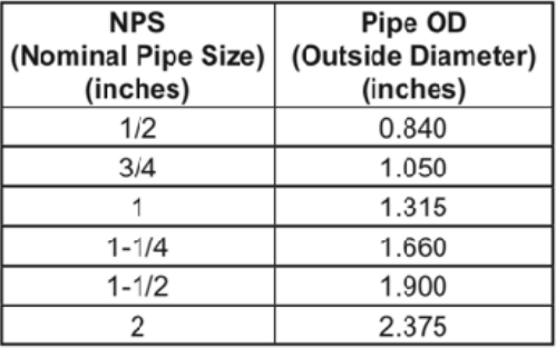
| Actual pipe diameters are larger than the rated size. |
2. Choose the Bending Die the same nominal pipe size as pipe to be bent. For example: use the 1/2" Bending Die with the size marked on it with 1/2" NPS pipe.
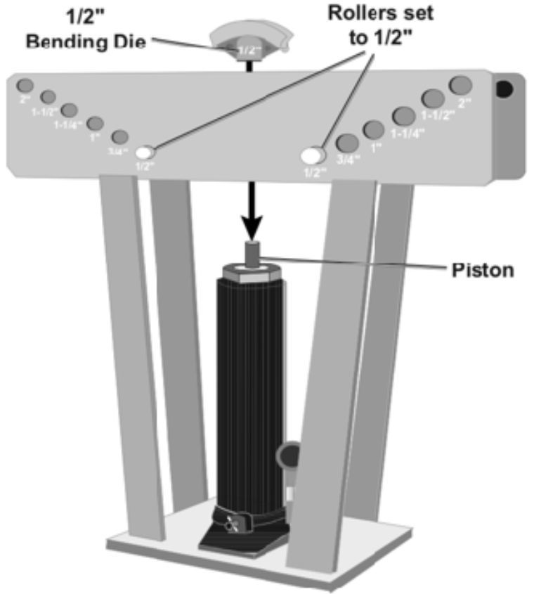
3. Attach the Bending Die to the Piston and move the rollers to the holes with the corresponding size. e.g. For 1/2” bending die, place the rollers in the holes marked 1/2”.
4. Mark center line of the bend on the pipe. Chalk or Sharpie markers work well.
| |
|---|---|
| Inserting the die into the hydraulic pipe bender |
5. Slide the pipe into the Bending Die and align. The mark on the pipe should align with the center of the Bending Die.
6. Place the Ram Handle over the Release Valve. Twist the Release Valve clockwise to close the valve.
7. Insert the Ram Handle into the fulcrum. Pump until the pipe reaches the Bending Die.
8. Continue pumping SLOWLY until the desired angle is reached.
- Remember that steel has some spring to it. You may need to slightly over-bend your pipe to achieve a desired angle.
- It may be helpful to practice on scrap first.
9. Place the Ram Handle over the Release Valve, turn counterclockwise to lower the piston and remove the pipe.
| |
|---|---|
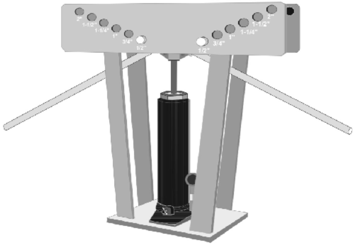
| Bending the pipe |
10. Remove the Bending Dies, clean the work area, and put the equipment away when finished.
| |
|---|---|
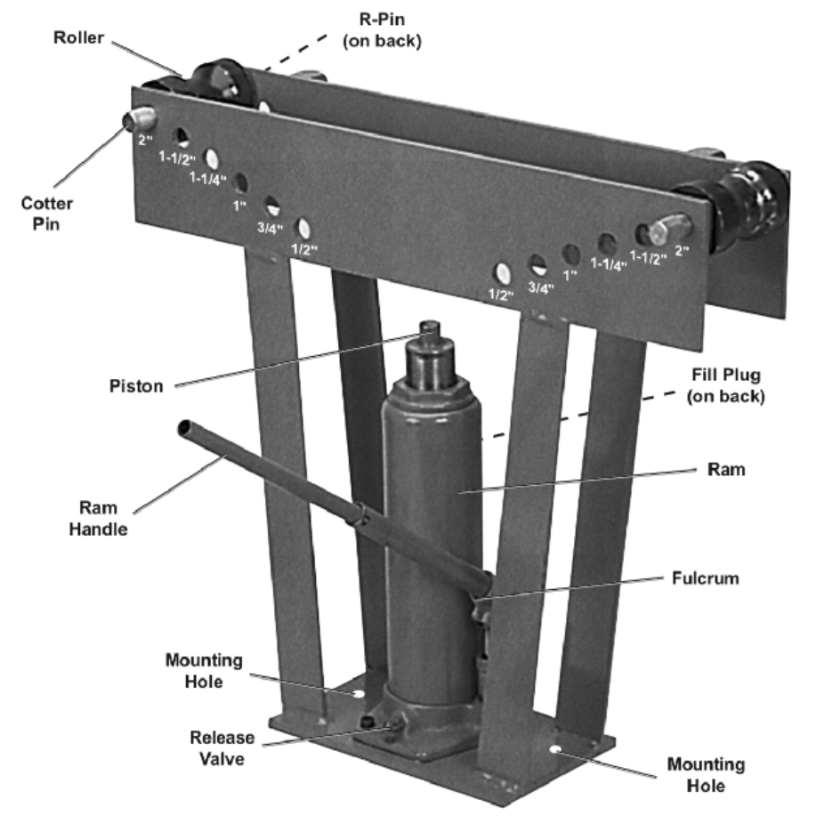
| The hydraulic pipe bender with parts labeled |
