Compact Bender: Difference between revisions
No edit summary |
No edit summary |
||
| Line 70: | Line 70: | ||
* Make sure the mount fully engages with the acorn table’s lip. Tap down with a mallet if needed. | * Make sure the mount fully engages with the acorn table’s lip. Tap down with a mallet if needed. | ||
3. Choose the accessories appropriate to your operation and install them according to the [https://drive.google.com/file/d/1a4pH3CjFhws0Sr3z2NsYLwpn5r7BYovw/view?usp=drive_link Quick Set-up Guide.] | |||
* The Square Stop Block creates curved bends, and the Right Angle Attachment creates angles. | |||
{| class="infobox" cellspacing="5" style="width: 22em; text-align: left; font-size: 100%; line-height: 1.5em;" | {| class="infobox" cellspacing="5" style="width: 22em; text-align: left; font-size: 100%; line-height: 1.5em;" | ||
! colspan="2" class="infobox-image" | [[File:Compact_bender_stop_block.png| | ! colspan="2" class="infobox-image" | [[File:Compact_bender_stop_block.png|150px|stop blocks ]] | ||
|- | |- | ||
| colspan="2" | Stop block orientation options | | colspan="2" | Stop block orientation options | ||
|- | |- | ||
|} | |} | ||
* The Support Pin lifts these accessories just enough to prevent interference with handle movement while bending the workpiece. | * The Support Pin lifts these accessories just enough to prevent interference with handle movement while bending the workpiece. | ||
| Line 87: | Line 87: | ||
{| class="infobox" cellspacing="5" style="width: 22em; text-align: left; font-size: 100%; line-height: 1.5em;" | {| class="infobox" cellspacing="5" style="width: 22em; text-align: left; font-size: 100%; line-height: 1.5em;" | ||
! colspan="2" class="infobox-image" | [[File:Compact_bender_setup_guide_sketch.png| | ! colspan="2" class="infobox-image" | [[File:Compact_bender_setup_guide_sketch.png|750px|setup guide sketch ]] | ||
|- | |- | ||
| colspan="2" | Compact Bender quick set-up guide | | colspan="2" | Compact Bender quick set-up guide | ||
Revision as of 20:24, 7 February 2024
| Compact Bender | |
|---|---|
| General Info | |
| Make | Central Machinery (Harbor Tools) |
| Model | |
| Serial | Unknown |
| Specs | n/a |
| Manual | Manual |
| Asylum Info | |
| Location | Metal Shop |
| Rubric | n/a |
| Training | Tool classes |
| Testing | Tool testing, or [[:Category:Metal Shop#Tool Testing
Night|come to the shop on Tool Testing Night]] |
| Restrictions | green |
Use for:
- Bending rod and flat bar sized within the range of the machine’s capacity.
- 1-15/16” Max Stock Width
- 5/16” Max Stock Thickness
- 5/8” Max Bar Diameter
- Bends curves and “sharp”angles.
Do Not Use for:
- Bending welded or excessively work hardened metals.
Hazard Analysis
- Metal can snap while bending, and flakes of rust, mill scale, or paint can become airborne. Eye protection
required.
- Pinched fingers, skin.
- Cuts / Scrapes from sharp cut edges of the workpiece.
- Cuts / Scrapes / bruises if care is not taken to prevent metal stock from slipping during the
bending process.
| Eye protection required! | ||
|---|---|---|
Operation Notes
- The shop-made mount slips onto the outer lip of the acorn table without the need for additional fasteners.
- This tool, purchased at Harbor Freight, will struggle if you exceed its capacity. Please treat it kindly.
- Max. Stock Width: 1- 15/16”
- Max Stock Thickness: 5/16”
- Max Bar Stock Diameter: 5/8”

| |
|---|---|
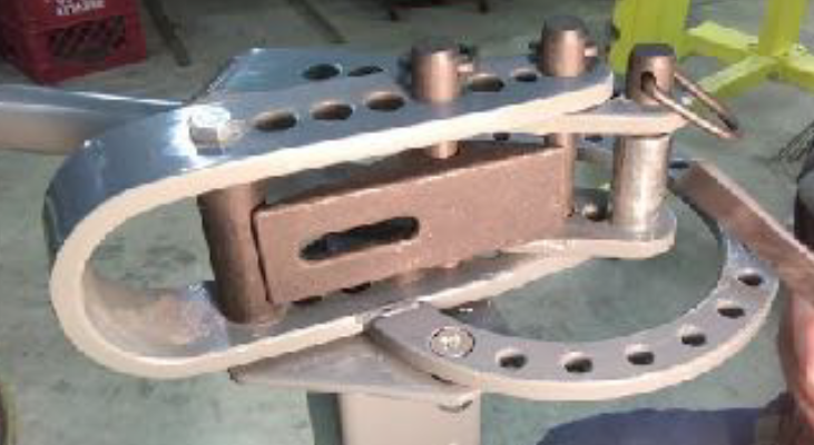
| Parts of the Compact Bender |
- For detailed instructions on bending hooks, handles, and alphabet shapes, refer to the =instruction booklet provided by the manufacturer. (Paper copy available in the metal shop.)
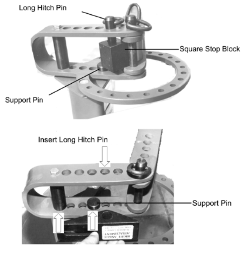
- Accessories are stored in a red bin stored in the metal shop. Accessories include seven round dies, 3 hitch pins, a right angle bending attachment, and a couple of shop-made replacement pieces (square stop block and a support pin).
Basic Operation Instructions
1. Check to make sure the screws attaching the bender to the shop-made mount are secure.
2. Place the mount on the lip of the acorn table.
- The acorn table corner closest to the belt sander works best.
- Make sure the mount fully engages with the acorn table’s lip. Tap down with a mallet if needed.
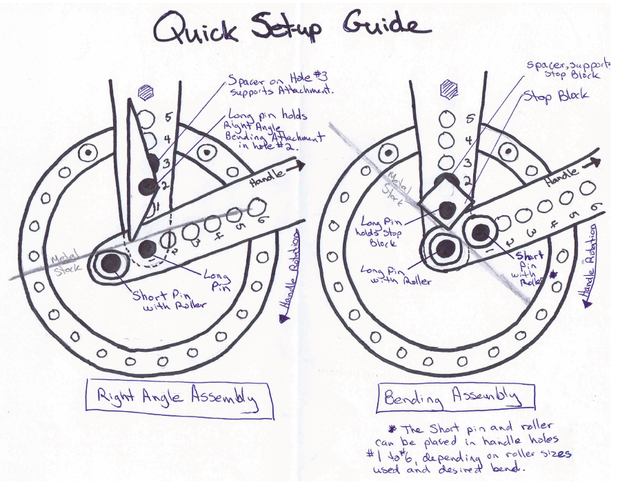
3. Choose the accessories appropriate to your operation and install them according to the Quick Set-up Guide.
- The Square Stop Block creates curved bends, and the Right Angle Attachment creates angles.

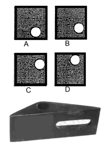
| |
|---|---|
| Stop block orientation options |
- The Support Pin lifts these accessories just enough to prevent interference with handle movement while bending the workpiece.
During set up, position the handle on the right side, up and out of the way. This will simplify roller installation.

| |
|---|---|
| Compact Bender quick set-up guide |
- Insert rollers and pins. Reserve the short pin for roller placement on the handle assembly. (See Quick Set Up Guide)
- The Square Stop Block has four positions to accommodate the thickness of your stock.
- Always place hole on the right in order to prevent the block from turning while the bend is performed.
4. Insert stock into bender, position it, and pull on handle to complete the bend.
5. Optional: For repeat bends, place stop pins into the ring located below the handle.
6. If needed, pins and rollers can be disassembled to remove bent stock from bender.
