Brackets Tutorial 4: Basic Cardboard Aided Design: Difference between revisions
No edit summary |
|||
| (41 intermediate revisions by the same user not shown) | |||
| Line 5: | Line 5: | ||
=Introduction= | =Introduction= | ||
Some people may find it easier to make a cardboard prototype of a sheet metal part rather than designing it in CAD. This tutorial shows how to convert a cardboard prototype into an image file and upload it to the CNC plasma cutter. | Some people may find it easier to make a cardboard prototype of a sheet metal part rather than designing it in CAD. This tutorial shows how to convert a cardboard prototype into an image file and upload it to the [[:Category:Plasma Shop | CNC plasma cutter]]. | ||
We will be making a bracket to hold the E-STOP button to the frame of the | We will be making a bracket to hold the E-STOP button to the frame of the plasmatron. It will be cut from 10-Gauge mild steel, ensuring it will be 1,000 times stronger than it needs to be. This done to show how very sturdy parts can be made using this method, not out of any need for this particular part. | ||
=Prototyping= | =Prototyping= | ||
| Line 13: | Line 13: | ||
If you don't have the time or the inclination to use a CAD system or a 3D printer, you can perform what we call "Rapid Prototyping" using drafting tools and paints. | If you don't have the time or the inclination to use a CAD system or a 3D printer, you can perform what we call "Rapid Prototyping" using drafting tools and paints. | ||
Cut a cardboard prototype as shown at actual size. Make sure it is colored either bright white or deep black to ease the scanning step. Note the dangling feature along the bottom edge, which is folded to make an angle brace. | Cut a cardboard prototype as shown at actual size. Make sure it is colored either bright white or deep black to ease the scanning step. Note the dangling feature along the bottom edge, which is folded to make an angle brace. It is flanked by incisions into the rectangle so the angle brace will fold into its slot and stay in the plane of the lower edge of the bracket. | ||
Holes are defined by drawing spots of the contrasting color. | The prototype has been painted white with acrylic paint. Holes are defined by drawing spots of the contrasting color. | ||
[[File:Tut4_cutting_cardboard.png|300px|cutting]] | [[File:Tut4_cutting_cardboard.png|300px|cutting]] | ||
| Line 75: | Line 75: | ||
Save the new image. This is what will be uploaded to Torchmate CAD. | Save the new image. This is what will be uploaded to Torchmate CAD. | ||
= | =Create a Tool Path= | ||
We will use the utility application Torchmate CAD 8 (TMCAD) to convert the image | We will use the utility application Torchmate CAD 8 (TMCAD) that resides on the driver computer for the CNC plasma cutter to convert the image into a tool path. Click on the Torchmate CAD icon [[File:TMCAD_icon.png|32px]] to start. | ||
A blank document will open. Click on the "File" menu and select "Import." | A blank document will open. Click on the "File" menu and select "Import." | ||
| Line 118: | Line 118: | ||
[[File:Tut4_dxf_export.png|center|700px|dxf export]] | [[File:Tut4_dxf_export.png|center|700px|dxf export]] | ||
= | =Cut the Part= | ||
The CNC plasma cutter at Artisans Asylum is an amazing tool that requires training and tool testing to use. Classes are available. Please consult the class list on the [[:Category:Metal_Shop | Metal Shop main page]] for offerings. | The [[:Category:Plasma Shop | CNC plasma cutter]] at Artisans Asylum is an amazing tool that requires training and tool testing to use. Classes are available. Please consult the class list on the [[:Category:Metal_Shop | Metal Shop main page]] for offerings. | ||
==Import the DXF file into Torchmate== | ==Import the DXF file into Torchmate== | ||
For a summary description of the use of the Torchmate software to set up a cut, please see [https://drive.google.com/file/d/1LLlutGdtLg0dI_iBPAtDAtusp5fTD988/view?usp=drive_link Chapter 3 of the Plasmatron Training Doc.] | |||
Double-click on the Torchmate 4 icon [[File:Torchmate_icon.png|32px]] to start. The first image to appear will ask whether or not you want to connect the software to the machine. You don't have to connect to process the data, but you will need to if you are going to cut the part. | |||
[[File:torchmate_connect_dialog.png|center|300px|torchmate connect]] | [[File:torchmate_connect_dialog.png|center|300px|torchmate connect]] | ||
A blank document window should open. Pull down the "File" menu and select "Import DXF." | |||
A file picker window will open allowing you to select the DXF file we created in the previous section. | |||
Once you hit "Open" another file picker window will appear. This gives you the option to specify a name and a location for the G-Code file that will be created. | |||
The process concludes with a third dialog box that allows you to specify different parameters for the converted tool path. | |||
[[File:Tut4_dxf_import_params_dialog.png|center|450px|TM DXF import params]] | |||
Among the most important features are the "Scale" factor in the upper left corner. To preserve the part dimensions, this must be 1.000. This is your last chance to change the scale of the part if you prefer. | |||
In the upper right corner, you can specify the cutting speed for the machine if you know it. This isn't necessary at this point: You have several opportunities to set it. | |||
Partway down the right margin, you can apply tool width compensation if you want it. If desired, select a tool number between 4 and 12. Tool 4 applies a compensation of 0.04" and so on like that. Tool 6 is the most commonly used one. | |||
Once you hit "Okay" the tool path should be displayed in the graphics window. | |||
==Set Up the Machine and Cut== | |||
For a detailed description of the operation of the CNC plasma cutter, please read the [https://drive.google.com/file/d/1PRsRqTug9Yh1PXNv7A6d63P6PcKDlWNf/view?usp=drive_link Training Document]. You will need to be tool-tested on this machine before you are permitted to operate it. | |||
* Assemble the nozzle package and install it on the torch. | |||
* Make sure the [[:Antwerp_Shop_Air | air compressor]] is turned on. | |||
* Switch on the power to the torch, the signal generator, and the torch-height controller. | |||
* Place a sheet of mild steel on the bed of the machine and jog the gantry over to an open section of the sheet. | |||
* Check the cutting parameters for the sheet material you are using. | |||
* Perform a dry run to make sure the tool path doesn't run off the edge of the sheet. | |||
*'''CUT!!!''' The sheet metal part is shown below alongside the cardboard pattern. | |||
[[File:Tut4_plasmatron_cutting_estop_bracket.png|425px|Cutting the part]] | |||
[[File:SW_gear_icon_tiny.png|6px|thin strip]] | |||
[[File:SW_gear_icon_tiny.png|6px|thin strip]] | |||
[[File:Tut4_cut_part_and_prototype.png|270px|Part and prototype]] | |||
=Finish the Bracket= | |||
The cut blank must be bent into shape and welded. Before bending, it is important to mark where the bends are to be made and to identify the side from which it is to be bent. It is very embarrassing to make an asymmetric part in the mirror-image of the intended shape and have to go through the whole process a second time. | |||
The main bend in the bracket is made with the [[:Hydraulic_Shop_Press | 12-ton shop press]]. | |||
Be careful not to bend it too far, it's very difficult to unbend even slightly. Check the part with a square. | |||
[[File:Tut4_marking_blank.png|250px|marking the blank]] | |||
[[File:SW_gear_icon_tiny.png|6px|thin strip]] | |||
[[File:Tut4_bending_on_shop_press.jpg|250px|bending]] | |||
[[File:SW_gear_icon_tiny.png|6px|thin strip]] | |||
[[File:Tut4_check_with_square.png|250px|check w square]] | |||
The diagonal brace is small enough that it can be bent into position with a hammer. | |||
Notice that there is some clearance between the tab on the corner brace and the slot it occupies. This is a convenient result from having selected the "Online" tool path in TMCAD with no tool compensation. The original prototype had no such clearance built in. | |||
[[File:Tut4_hammering.png|250px|hammering]] | |||
[[File:SW_gear_icon_tiny.png|6px|thin strip]] | |||
[[File:Tut4_corner_brace_in_pos.jpg|250px|in vise]] | |||
[[File:SW_gear_icon_tiny.png|6px|thin strip]] | |||
[[File:Tut4_corner_brace_bent_in.jpg|250px|brace_bent_in]] | |||
[[:Category:MIG_Welders | MIG welding]] is most convenient because it is easy to learn and quick to set up. These welders are <span style="color:red">red</span> tools. Training and tool-testing are required. | |||
The tab on the corner brace is joined by a single tiny weld that need not be beautiful. This is just a bracket. Nobody will ever look at it. | |||
[[File:Tut4_welding.png|240px|MIG welding]] | |||
[[File:SW_gear_icon_tiny.png|6px|thin strip]] | |||
[[File:Tut4_weld_on_brace.png|240px|weld on angle brace]] | |||
[[File:SW_gear_icon_tiny.png|6px|thin strip]] | |||
[[File:Tut4_plasmatron_ESTOP.jpg|300px|bracket in place]] | |||
Revision as of 17:58, 19 November 2024
Link to: Bracketage Main Page
Introduction
Some people may find it easier to make a cardboard prototype of a sheet metal part rather than designing it in CAD. This tutorial shows how to convert a cardboard prototype into an image file and upload it to the CNC plasma cutter.
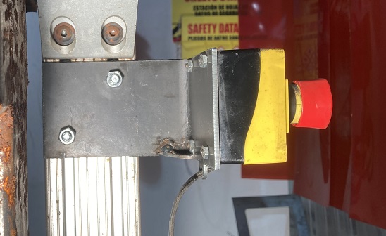
We will be making a bracket to hold the E-STOP button to the frame of the plasmatron. It will be cut from 10-Gauge mild steel, ensuring it will be 1,000 times stronger than it needs to be. This done to show how very sturdy parts can be made using this method, not out of any need for this particular part.
Prototyping
If you don't have the time or the inclination to use a CAD system or a 3D printer, you can perform what we call "Rapid Prototyping" using drafting tools and paints.
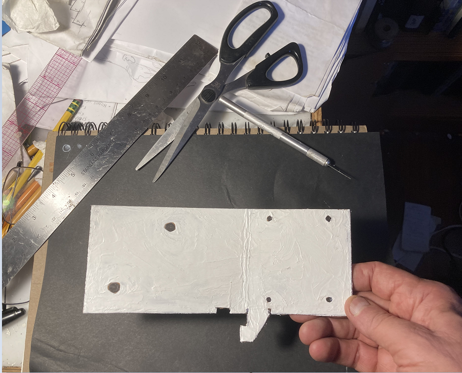
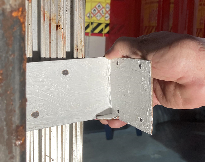
Cut a cardboard prototype as shown at actual size. Make sure it is colored either bright white or deep black to ease the scanning step. Note the dangling feature along the bottom edge, which is folded to make an angle brace. It is flanked by incisions into the rectangle so the angle brace will fold into its slot and stay in the plane of the lower edge of the bracket.
The prototype has been painted white with acrylic paint. Holes are defined by drawing spots of the contrasting color.
Image Processing
Scan the Prototype
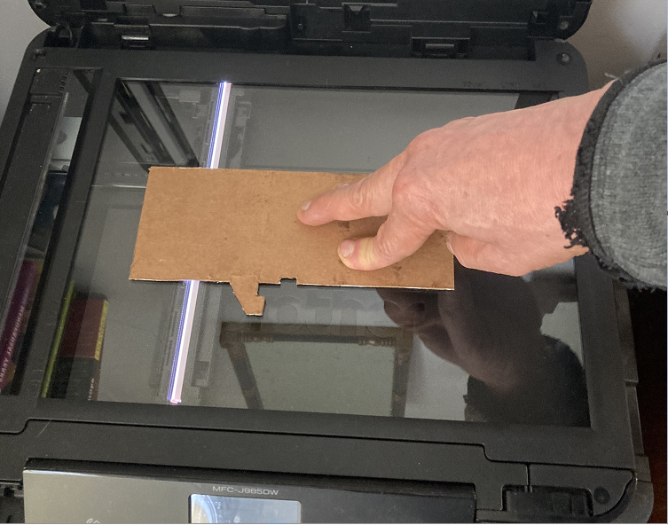
If the prototype is 8-1/2" x 11" or smaller, you can scan it on a regular flatbed scanner. This is particularly convenient because it preserves the original scale of the part.
If the prototype is larger than the bed of the scanner, you will need to scan it in sections and paste them together using a graphics utility such as Photoshop or Paint.
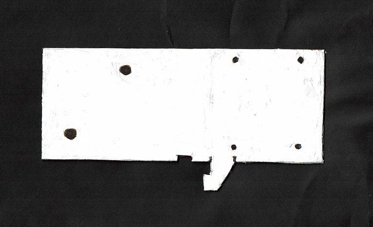
Please note: You will need to place a solid background over the prototype to make a good scan. The image shown left is just an illustration. The scanned image to the right was made with a black piece of paper over the cardboard, and the scanner cover closed.
Inverting the Contrast
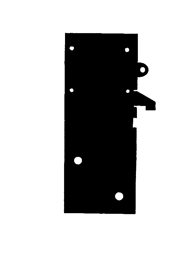
In the example shown, the cardboard prototype was painted white, with the holes marked in black. The Torchmate CAD utility program will only accept a black-on-white image.
For purposes of teaching, the bracket was designed this way. Of course it is possible to paint the cardboard black and use white ink to define the holes and skip the inversion step.
In this section we will show how to accentuate and reverse the image contrast using the "Paint" utility program as an example. The tools used should be available in a very wide variety of graphics utilities on any computer. if your graphics utility includes an "Invert" feature, you can use that instead of the following sequence.
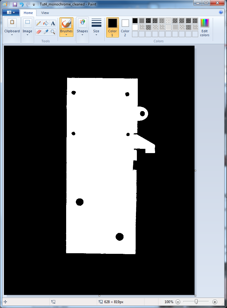
- First, you may need to clean up the image a bit. Open the scan and save it as a "monochrome bitmap."
Please note: The original scanned image has been modified to round out the circular holes and tidy up the edges. An ear has been added on the upper left edge. Note how the color options are limited when working with monochrome images.
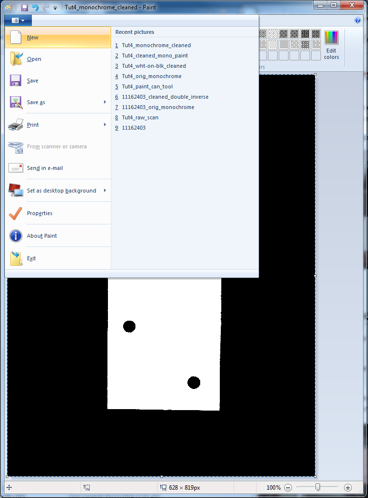
- Once the black-and-white image has been saved, select it (CTRL-A) and copy it to the clipboard (CTRL-C)
- Open the "File" menu and pick "New"
- The new file will open in full color. Paste the black-and-white version into the new window.
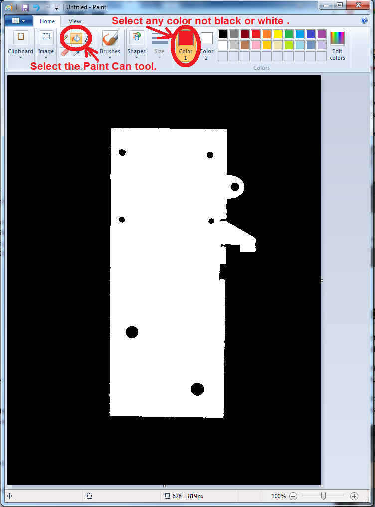
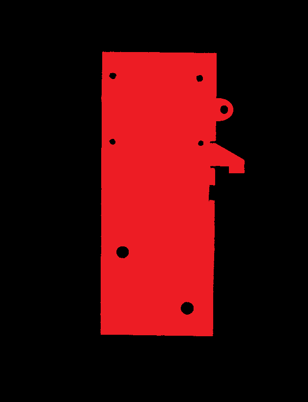
In the three images that follow, the "Paint Can" tool is used with the colors in sequence: RED, WHITE, BLACK to color the appropriate areas of the image. The body of the bracket should end up black; the space around it and also the holes should end up white.
Please note: This process only works cleanly with images that have passed through the conversion to monochrome. If you try this on a regular full-color JPEG the results won't be satisfactory.
Save the new image. This is what will be uploaded to Torchmate CAD.
Create a Tool Path
We will use the utility application Torchmate CAD 8 (TMCAD) that resides on the driver computer for the CNC plasma cutter to convert the image into a tool path. Click on the Torchmate CAD icon ![]() to start.
to start.
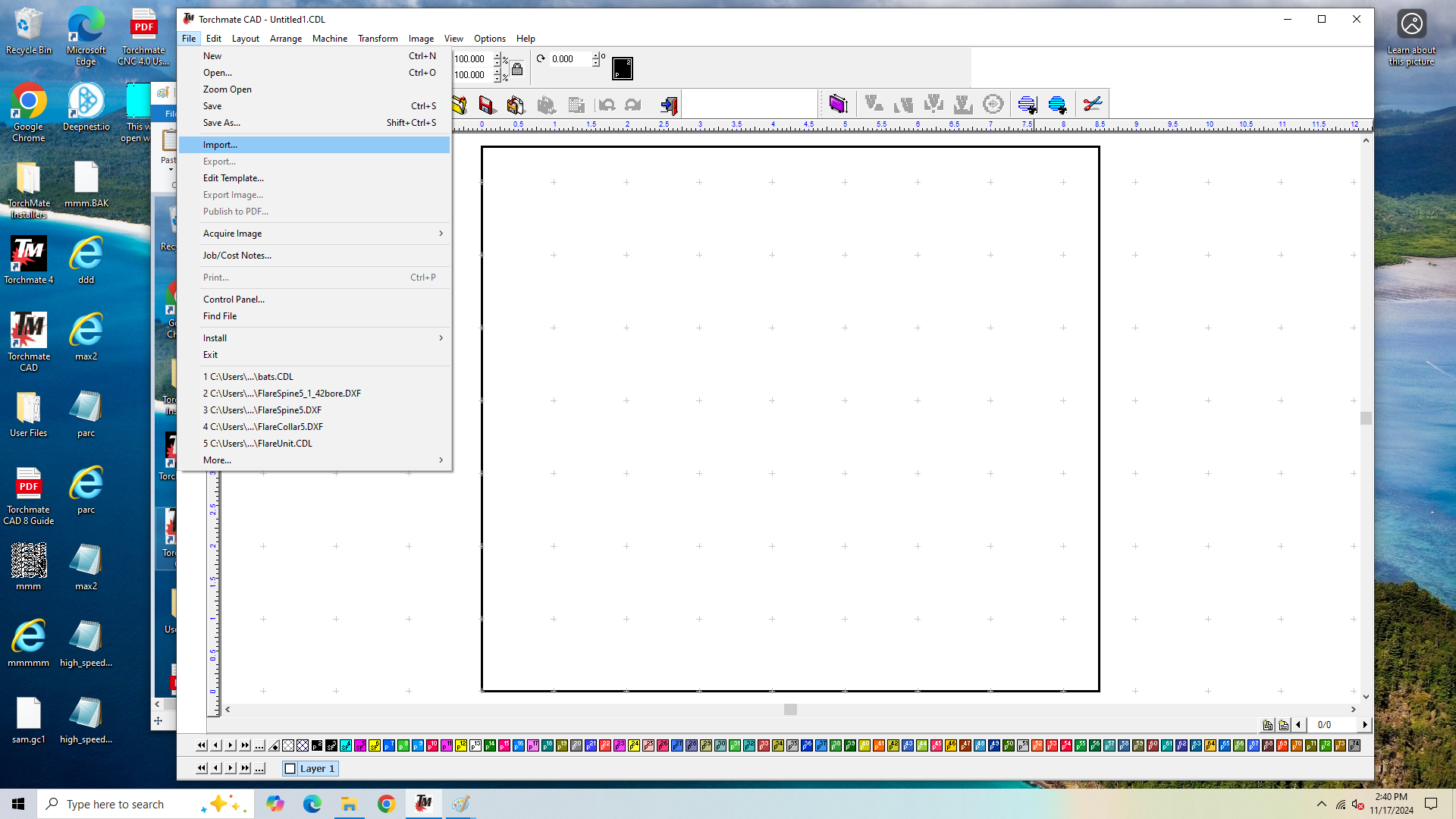
A blank document will open. Click on the "File" menu and select "Import."
A file picker window will open. Select the black-on-white scan file and click "Open."
The TMCAD window will show a small right-angle cursor ![]() to help locate the image on the desktop. When you click the left mouse button the image should appear below and to the right.
to help locate the image on the desktop. When you click the left mouse button the image should appear below and to the right.
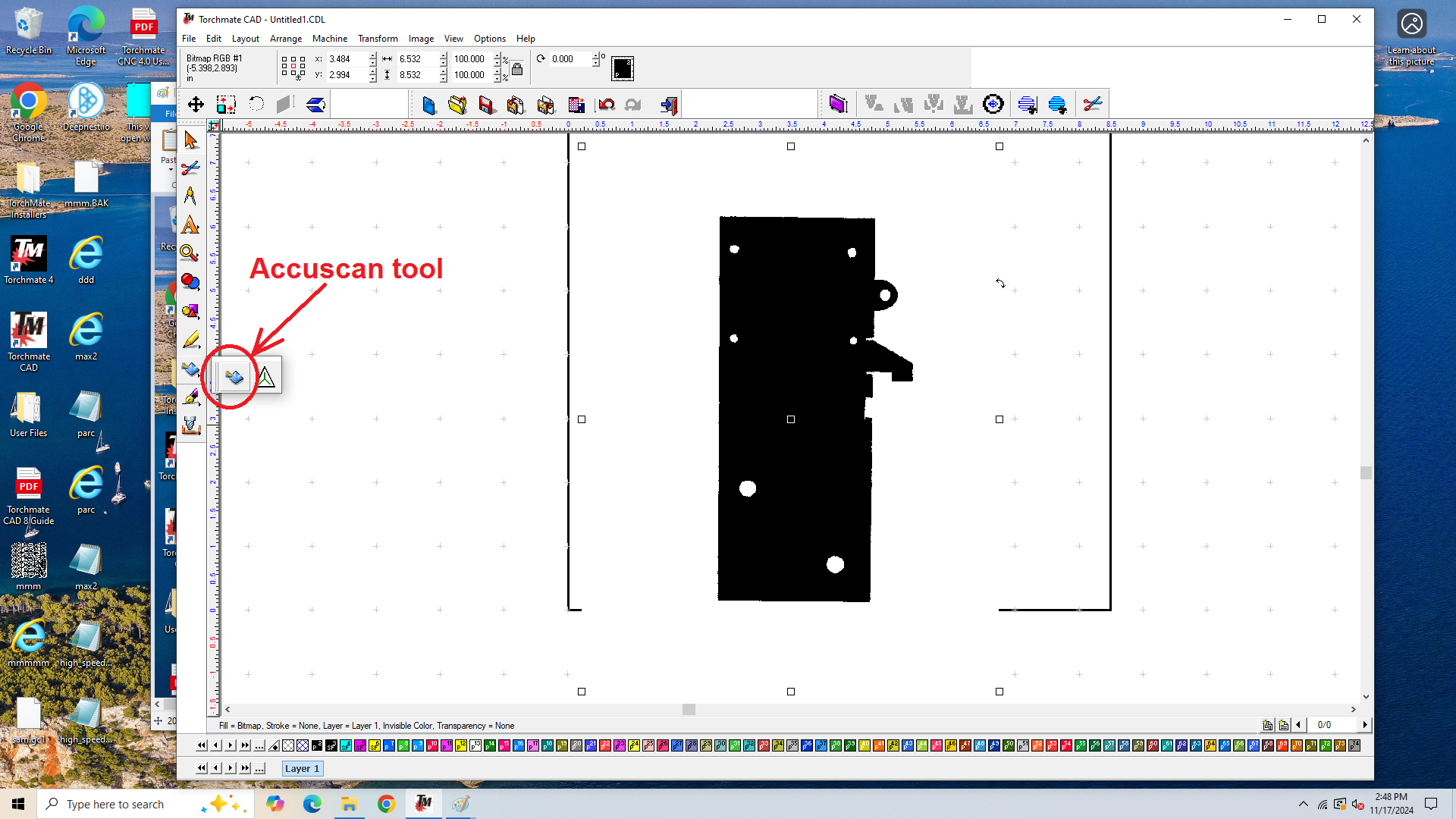
Select the "Accuscan" tool ![]() from the tool bar in the left margin.
from the tool bar in the left margin.
The use of the Accuscan tool is described on pp. 47-56 of the TMCAD user guide.
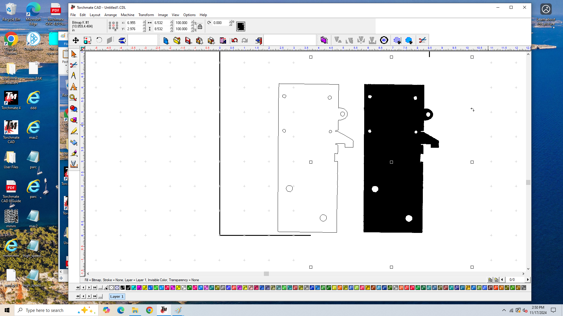
A new tool bar will appear just below the standard Windows menu bar. The important tool is near the right end, called "Vectorization." ![]() Click on it. This will create an outline of the black features in the selected image.
Click on it. This will create an outline of the black features in the selected image.
You can separate the two entities if you click the mouse on the image and drag it sideways. You can delete the solid image at this point, all you need is the outline.
Note: If you see two solid images instead of the view shown, go to the "View" menu and unselect the item "Show Fill".
From here on in the procedure is quite simple. Select the outline and verify the external dimensions coincide with your cardboard prototype. If you want to rotate it or change the scale you can do it here.
Make sure the outline is selected and pull down the "Arrange" menu. Select "Make Path."
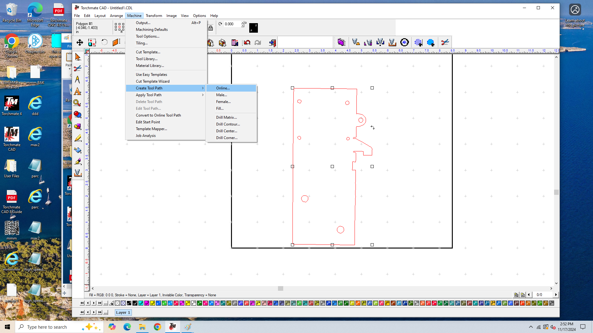
Next pull down the "Machine" menu and select "Create Tool Path." A popup sub-menu should appear. Choose one of the three options: "Online", "Male" and "Female." These determine how the tool width compensation is applied. Since this is an imprecise method, the "Online" option is probably the safest.
The tool path options are described on pp. 93-95 of the TMCAD user guide.
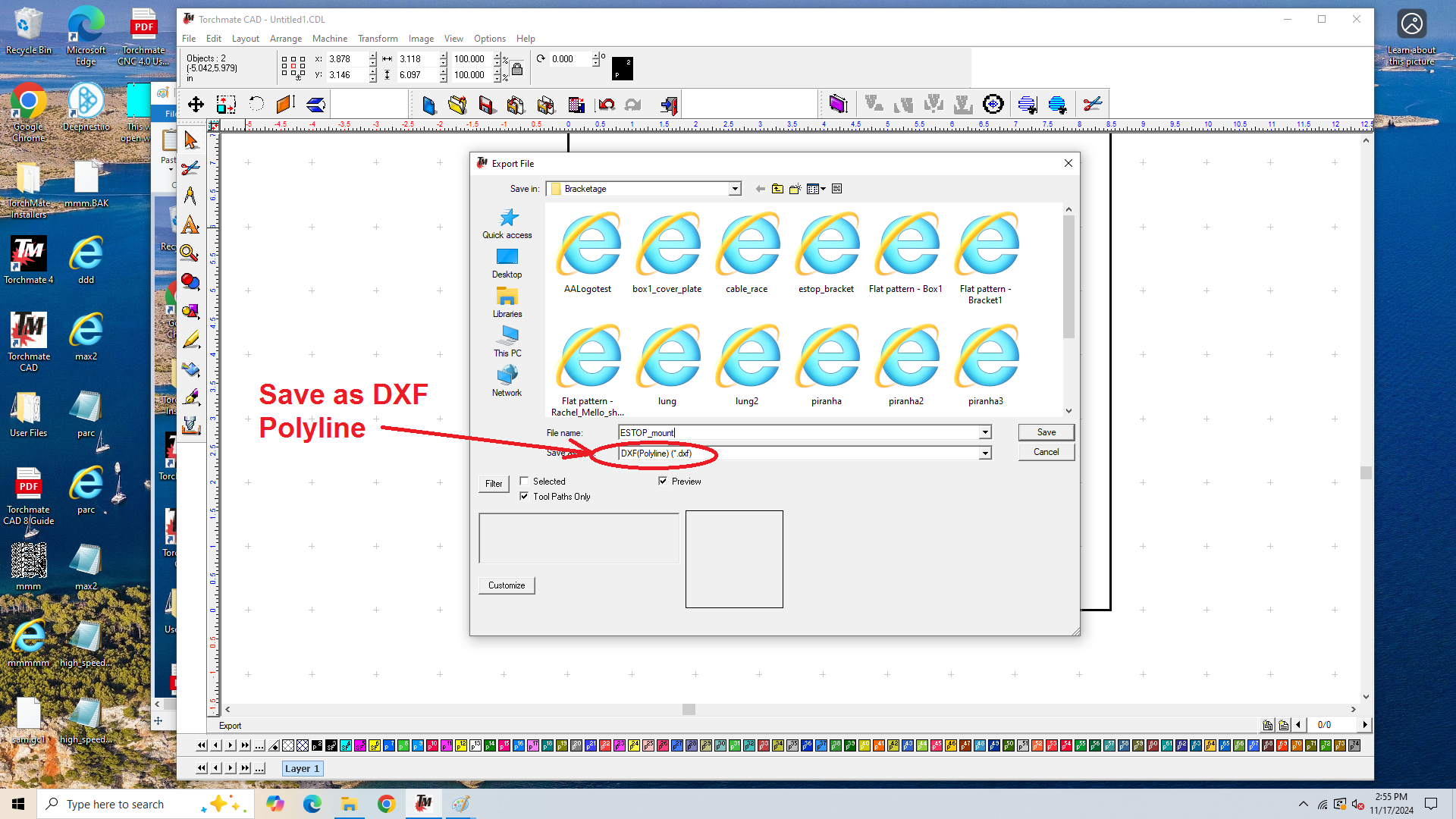
The last step in TMCAD is to pull down the "File" menu and select "Export..." Save the file as DXF, with the "Polyline" option. This is the most reliable.
Cut the Part
The CNC plasma cutter at Artisans Asylum is an amazing tool that requires training and tool testing to use. Classes are available. Please consult the class list on the Metal Shop main page for offerings.
Import the DXF file into Torchmate
For a summary description of the use of the Torchmate software to set up a cut, please see Chapter 3 of the Plasmatron Training Doc.
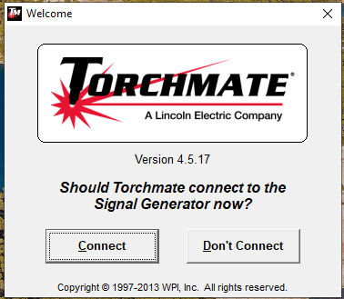
Double-click on the Torchmate 4 icon ![]() to start. The first image to appear will ask whether or not you want to connect the software to the machine. You don't have to connect to process the data, but you will need to if you are going to cut the part.
to start. The first image to appear will ask whether or not you want to connect the software to the machine. You don't have to connect to process the data, but you will need to if you are going to cut the part.
A blank document window should open. Pull down the "File" menu and select "Import DXF."
A file picker window will open allowing you to select the DXF file we created in the previous section.
Once you hit "Open" another file picker window will appear. This gives you the option to specify a name and a location for the G-Code file that will be created.
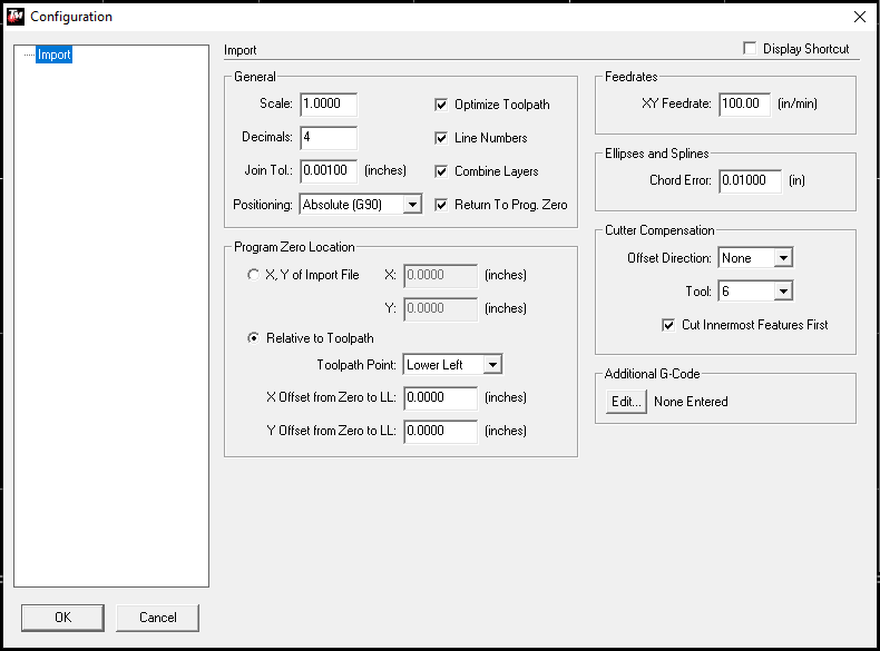
The process concludes with a third dialog box that allows you to specify different parameters for the converted tool path.
Among the most important features are the "Scale" factor in the upper left corner. To preserve the part dimensions, this must be 1.000. This is your last chance to change the scale of the part if you prefer.
In the upper right corner, you can specify the cutting speed for the machine if you know it. This isn't necessary at this point: You have several opportunities to set it.
Partway down the right margin, you can apply tool width compensation if you want it. If desired, select a tool number between 4 and 12. Tool 4 applies a compensation of 0.04" and so on like that. Tool 6 is the most commonly used one.
Once you hit "Okay" the tool path should be displayed in the graphics window.
Set Up the Machine and Cut
For a detailed description of the operation of the CNC plasma cutter, please read the Training Document. You will need to be tool-tested on this machine before you are permitted to operate it.
- Assemble the nozzle package and install it on the torch.
- Make sure the air compressor is turned on.
- Switch on the power to the torch, the signal generator, and the torch-height controller.
- Place a sheet of mild steel on the bed of the machine and jog the gantry over to an open section of the sheet.
- Check the cutting parameters for the sheet material you are using.
- Perform a dry run to make sure the tool path doesn't run off the edge of the sheet.
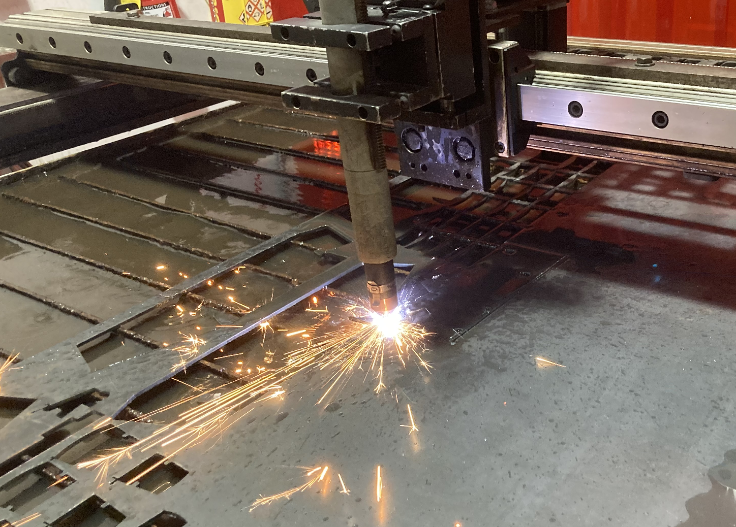
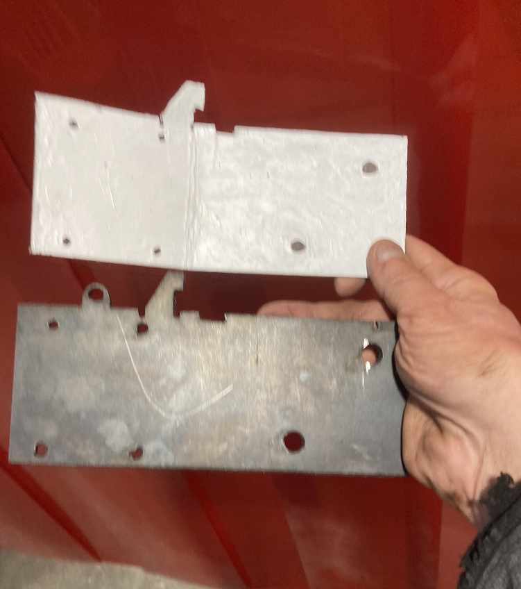
- CUT!!! The sheet metal part is shown below alongside the cardboard pattern.
Finish the Bracket
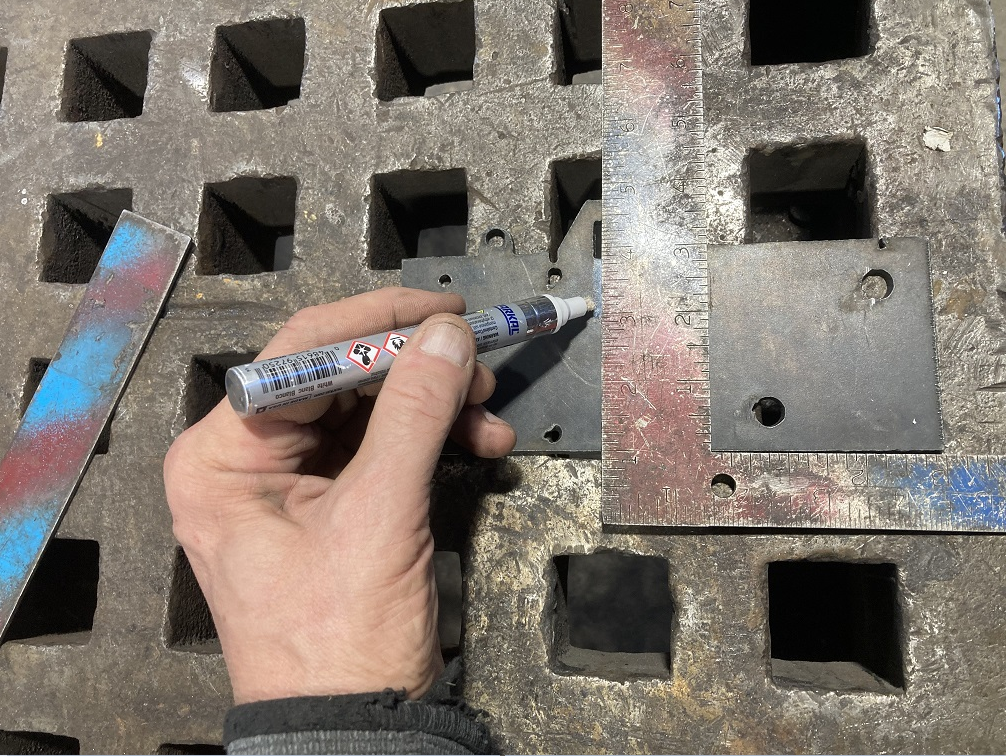
The cut blank must be bent into shape and welded. Before bending, it is important to mark where the bends are to be made and to identify the side from which it is to be bent. It is very embarrassing to make an asymmetric part in the mirror-image of the intended shape and have to go through the whole process a second time.
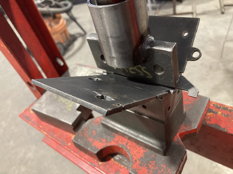
The main bend in the bracket is made with the 12-ton shop press.
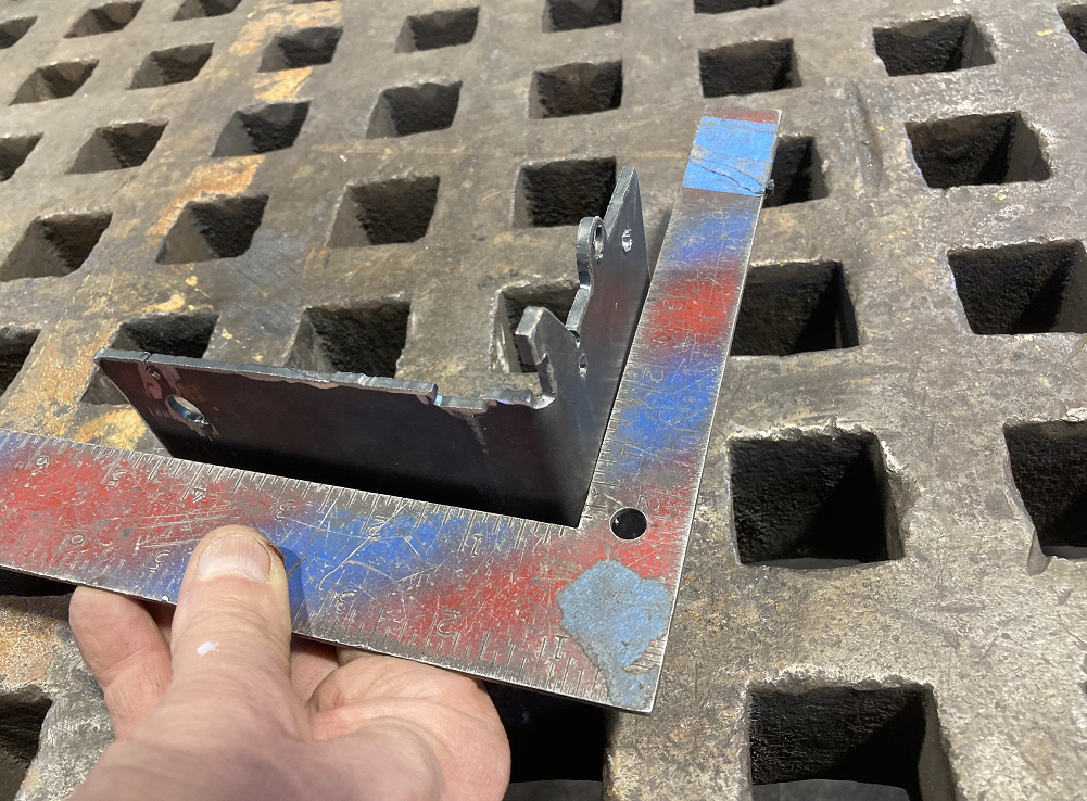
Be careful not to bend it too far, it's very difficult to unbend even slightly. Check the part with a square.
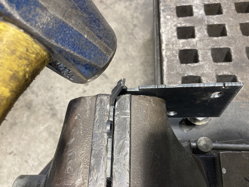
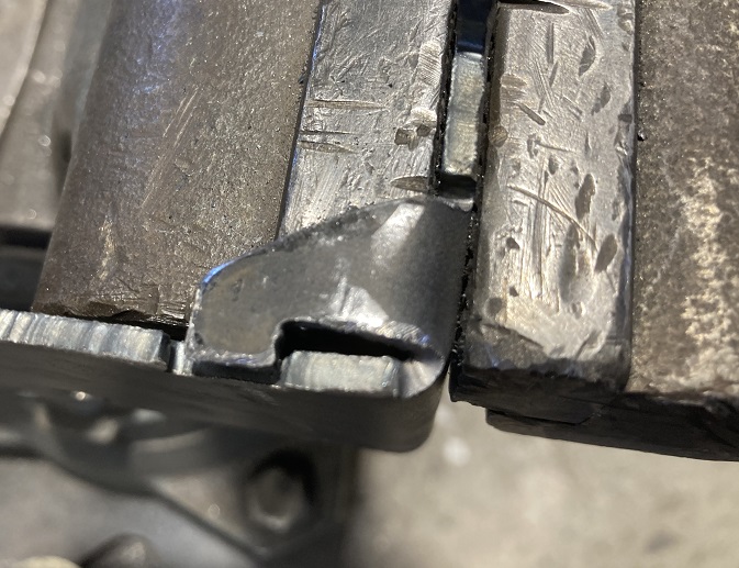
The diagonal brace is small enough that it can be bent into position with a hammer.
Notice that there is some clearance between the tab on the corner brace and the slot it occupies. This is a convenient result from having selected the "Online" tool path in TMCAD with no tool compensation. The original prototype had no such clearance built in.
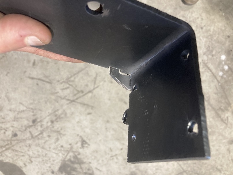
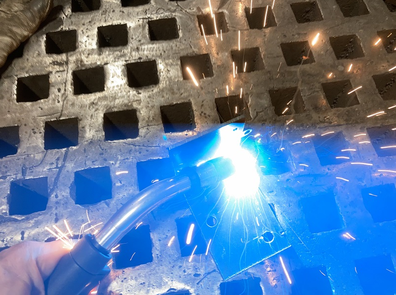
MIG welding is most convenient because it is easy to learn and quick to set up. These welders are red tools. Training and tool-testing are required.
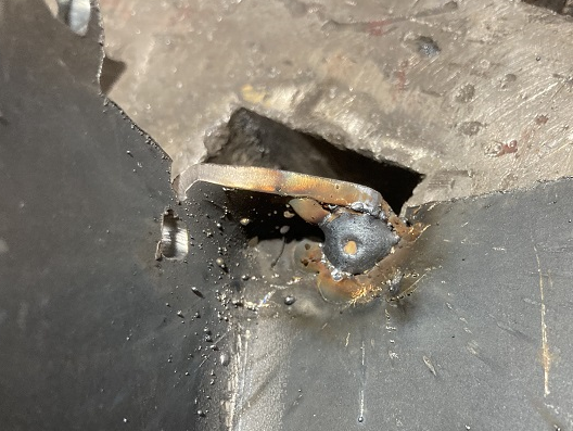
The tab on the corner brace is joined by a single tiny weld that need not be beautiful. This is just a bracket. Nobody will ever look at it.
