Brackets Tutorial 4: Basic Cardboard Aided Design: Difference between revisions
No edit summary |
|||
| Line 6: | Line 6: | ||
Some people may find it easier to make a cardboard prototype of a sheet metal part rather than designing it in CAD. This tutorial shows how to convert a cardboard prototype into an image file and upload it to the CNC plasma cutter. | Some people may find it easier to make a cardboard prototype of a sheet metal part rather than designing it in CAD. This tutorial shows how to convert a cardboard prototype into an image file and upload it to the CNC plasma cutter. | ||
We will be making a bracket to hold the E-STOP button to the frame of the CNC plasma cutter. | |||
=Prototyping= | =Prototyping= | ||
Revision as of 11:41, 18 November 2024
Link to: Bracketage Main Page
Introduction
Some people may find it easier to make a cardboard prototype of a sheet metal part rather than designing it in CAD. This tutorial shows how to convert a cardboard prototype into an image file and upload it to the CNC plasma cutter.
We will be making a bracket to hold the E-STOP button to the frame of the CNC plasma cutter.
Prototyping
If you don't have the time or the inclination to use a CAD system or a 3D printer, you can perform what we call "Rapid Prototyping" using drafting tools and paints.
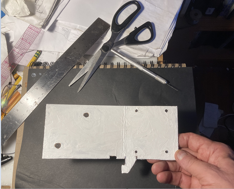
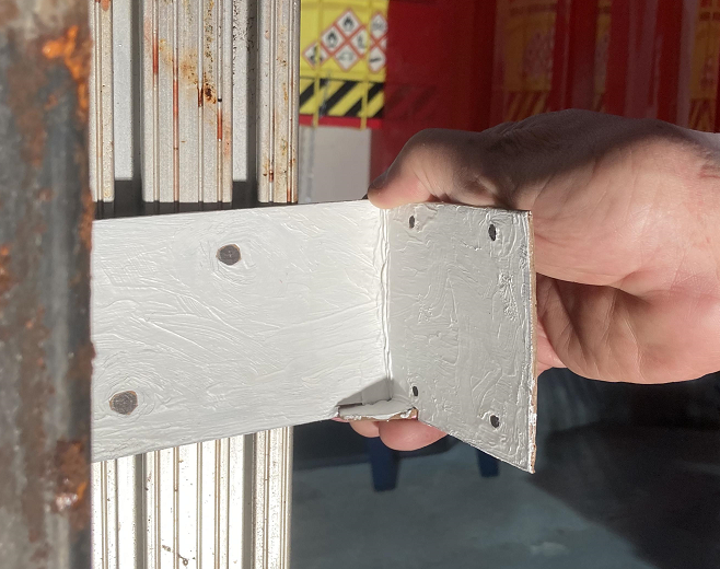
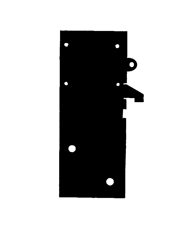
Cut a cardboard prototype as shown at actual size. Make sure it is colored either bright white or deep black to ease the scanning step. Note the dangling feature along the bottom edge, which is folded to make an angle brace.
Holes are defined by drawing spots of the contrasting color.
Image Processing
Scan the Prototype
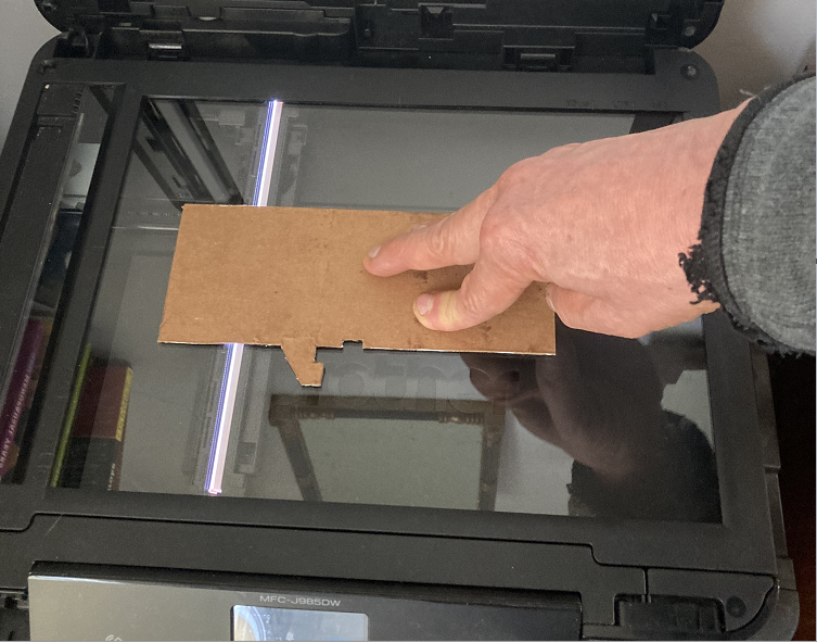
If the prototype is 8-1/2" x 11" or smaller, you can scan it on a regular flatbed scanner. This is particularly convenient because it preserves the original scale of the part.
If the prototype is larger than the bed of the scanner, you will need to scan it in sections and paste them together using a graphics utility such as Photoshop or Paint.
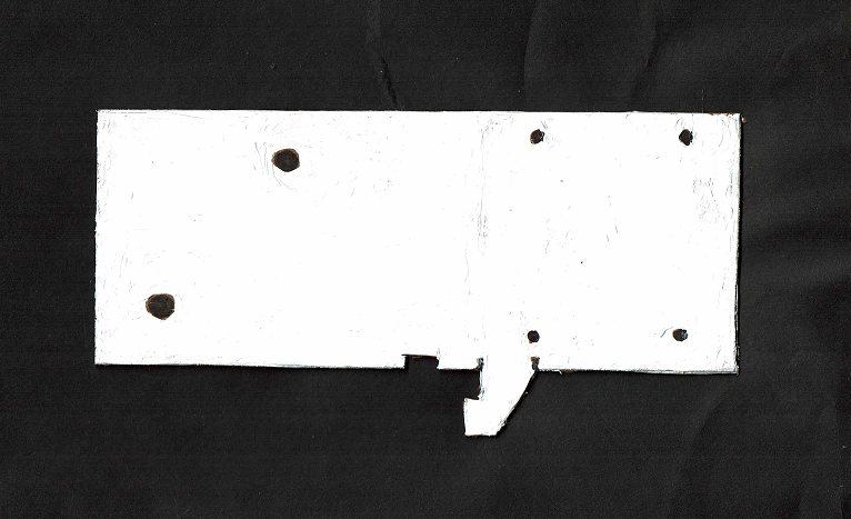
Please note: You will need to place a solid background over the prototype to make a good scan. The image shown left is just an illustration. The scanned image to the right was made with a black piece of paper over the cardboard, and the scanner cover closed.
Inverting the Contrast
In the example shown, the cardboard prototype was painted white, with the holes marked in black. The Torchmate CAD utility program will only accept a black-on-white image.
For purposes of teaching, the bracket was designed this way. Of course it is possible to paint the cardboard black and use white ink to define the holes and skip the inversion step.
In this section we will show how to accentuate and reverse the image contrast using the "Paint" utility program as an example. The tools used should be available in a very wide variety of graphics utilities on any computer. if your graphics utility includes an "Invert" feature, you can use that instead of the following sequence.
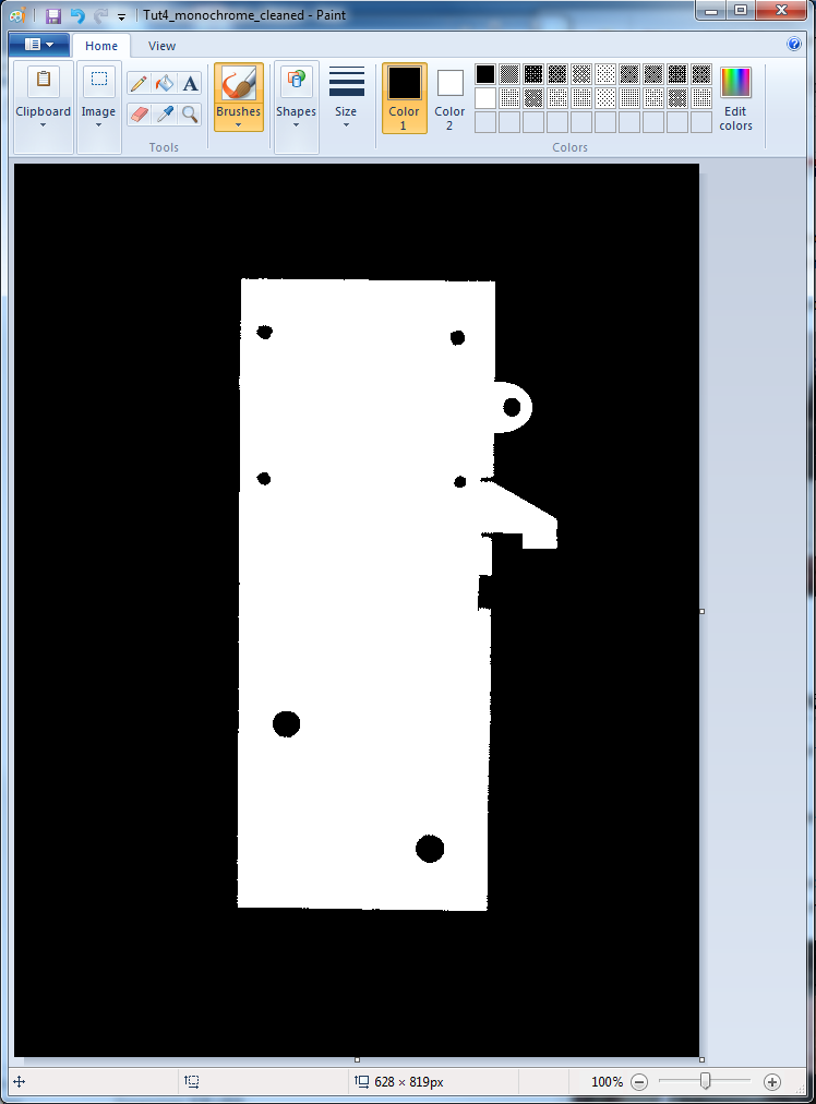
- First, you may need to clean up the image a bit. Open the scan and save it as a "monochrome bitmap."
Please note: The original scanned image has been modified to round out the circular holes and tidy up the edges. An ear has been added on the upper left edge. Note how the color options are limited when working with monochrome images.
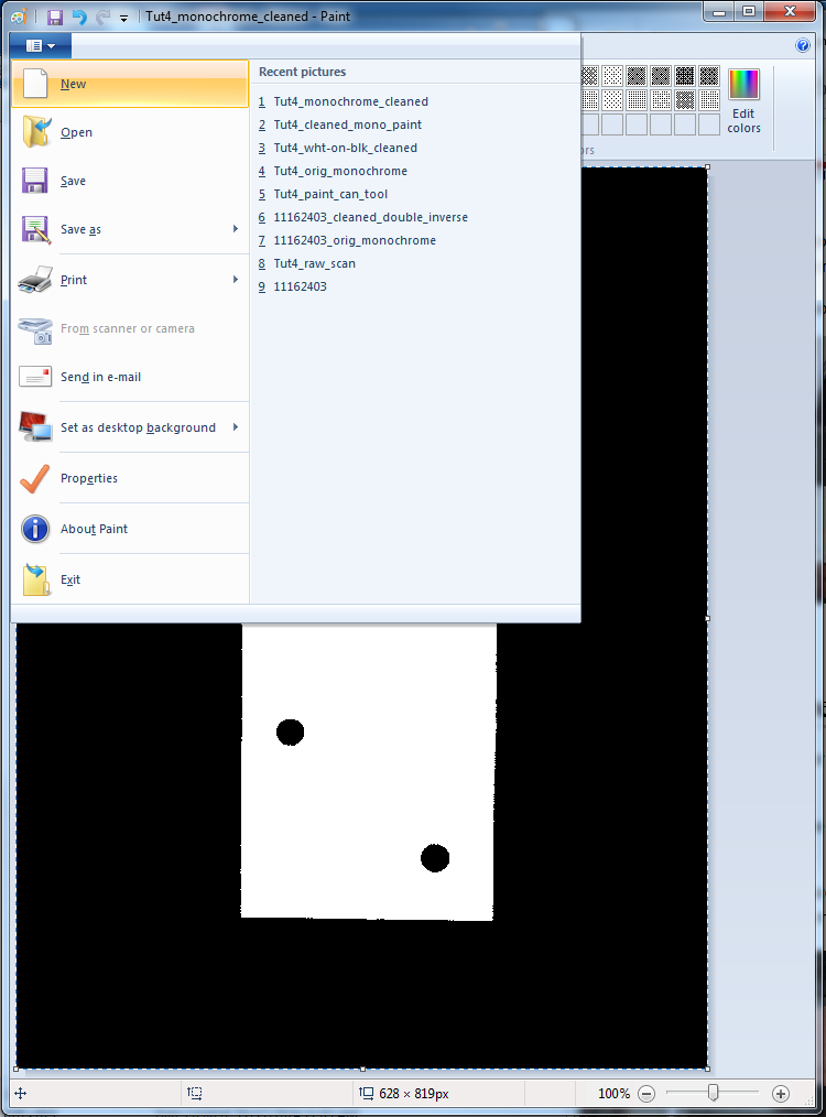
- Once the black-and-white image has been saved, select it (CTRL-A) and copy it to the clipboard (CTRL-C)
- Open the "File" menu and pick "New"
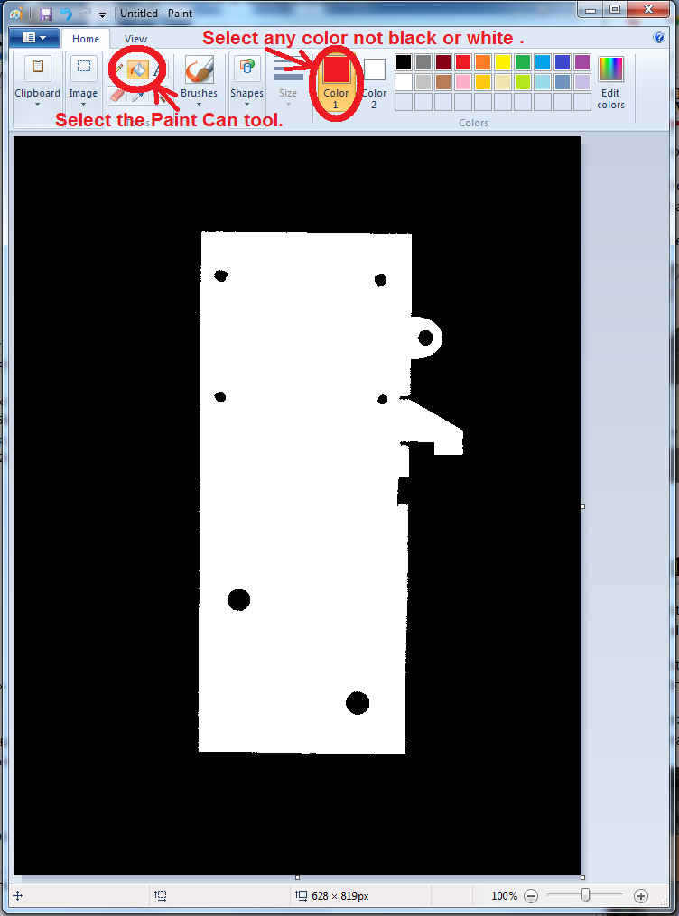
- The new file will open in full color. Paste the black-and-white version into the new window.
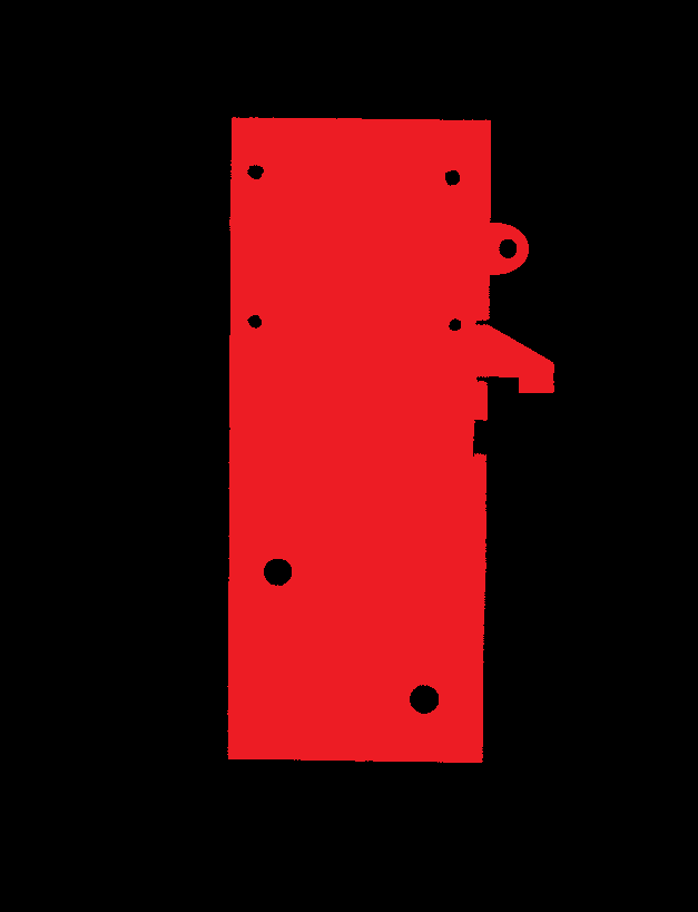
In the three images that follow, the "Paint Can" tool is used with the colors in sequence: RED, WHITE, BLACK to color the appropriate areas of the image. The body of the bracket should end up black; the space around it and also the holes should end up white.
Please note: This process only works cleanly with images that have passed through the conversion to monochrome. If you try this on a regular full-color JPEG the results won't be satisfactory.
Save the new image. This is what will be uploaded to Torchmate CAD.
Creating a Tool Path
We will use the utility application Torchmate CAD 8 (TMCAD) to convert the image file into a tool path for the CNC plasma cutter. Click on the Torchmate CAD icon ![]() to start.
to start.
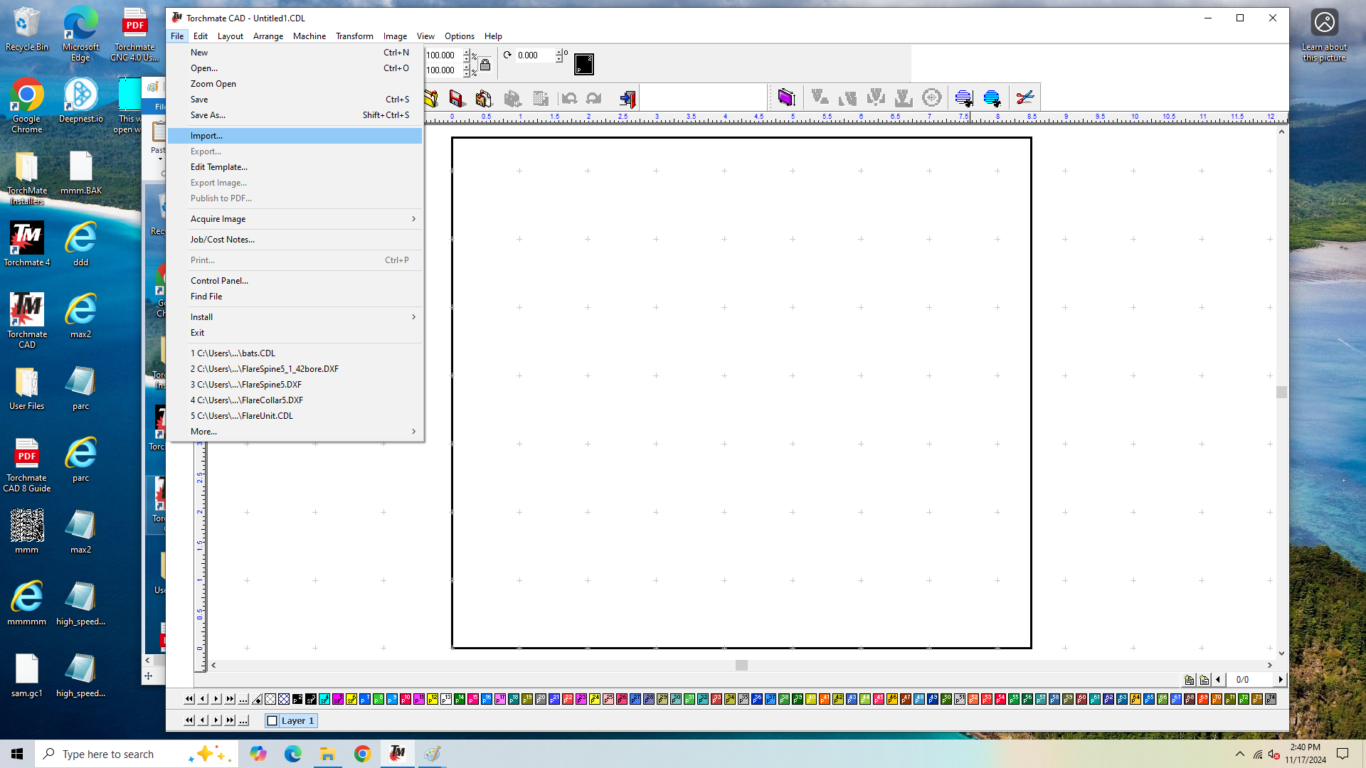
A blank document will open. Click on the "File" menu and select "Import."
A file picker window will open. Select the black-on-white scan file and click "Open."
The TMCAD window will show a small right-angle cursor ![]() to help locate the image on the desktop. When you click the image should appear.
to help locate the image on the desktop. When you click the image should appear.
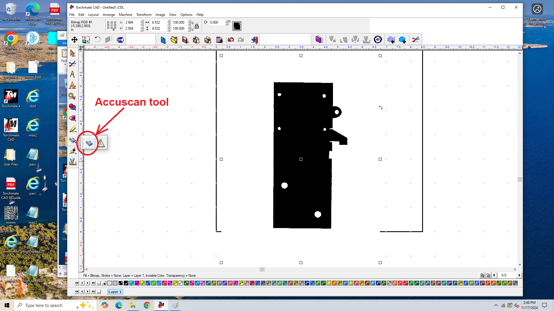
Select the "Accuscan" tool ![]() from the tool bar in the left margin.
from the tool bar in the left margin.
The use of the Accuscan tool is described on pp. 47-56 of the TMCAD user guide.
A new tool bar will appear just below the standard Windows menu bar. The important tool is near the right end, called "Vectorization." Click on it. This will create an outline of the black features in the selected image.
