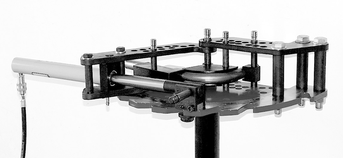
JD Squared Air Assisted Bender: Difference between revisions
From Artisans Asylum Wiki
No edit summary |
No edit summary |
||
| Line 76: | Line 76: | ||
{| class="infobox" cellspacing="5" style="width: 22em; text-align: left; font-size: 100%; line-height: 1.5em;" | {| class="infobox" cellspacing="5" style="width: 22em; text-align: left; font-size: 100%; line-height: 1.5em;" | ||
! colspan="2" class="infobox-image" | [[File:J_D_squared_bender_follow_bar.png| | ! colspan="2" class="infobox-image" | [[File:J_D_squared_bender_follow_bar.png|250px|follow bar ]] | ||
|- | |- | ||
| colspan="2" | Detail of the Follow Bar | | colspan="2" | Detail of the Follow Bar | ||
| Line 91: | Line 91: | ||
{| class="infobox" cellspacing="5" style="width: 22em; text-align: left; font-size: 100%; line-height: 1.5em;" | {| class="infobox" cellspacing="5" style="width: 22em; text-align: left; font-size: 100%; line-height: 1.5em;" | ||
! colspan="2" class="infobox-image" | [[File:J_D_squared_bender_workpiece_setup.png| | ! colspan="2" class="infobox-image" | [[File:J_D_squared_bender_workpiece_setup.png|500px|workpiece setup ]] | ||
|- | |- | ||
| colspan="2" | Correct Set-Up of the Workpiece with the Forming Die. | | colspan="2" | Correct Set-Up of the Workpiece with the Forming Die. | ||
Revision as of 16:52, 7 February 2024
| JD Squared Tube Bender | |
|---|---|
| General Info | |
| Make | JD Squared |
| Model | Model 4 |
| Serial | Unknown |
| Specs | n/a |
| Manual | Manual |
| Asylum Info | |
| Location | Metal Shop |
| Rubric | n/a |
| Training | Tool classes |
| Testing | Tool testing, or [[:Category:Metal Shop#Tool Testing
Night|come to the shop on Tool Testing Night]] |
| Restrictions | green |
Use for:
- Rolling / bending metal tube (measured by outside diameter).
- Equipped with .5 inch, .75 inch, 1 inch, and 1.25 inch diameter die sets.
- Thin-wall tube is this machine’s forte.
Do Not Use for:
- Wrong tube sizes with a given die set. Die sets are specific to tube size.
- Do not use for pipe. Tube is sized by outside diameter, pipe by its theoretical inside diameter.
Hazard Analysis
- Eye protection required. (Metal can snap while bending, and flakes of rust, mill scale, or paint can become airborne.
- Cuts / Scrapes from sharp cut edges of workpiece. Use of gloves is acceptable when using this machine.
- Cuts / Scrapes / bruises or worse if care is not taken to prevent metal stock from slipping during the bending process, possibly becoming airborne due to high pressure.
- Pinched fingers or skin.
| Eye protection required! | ||
|---|---|---|
Notes and Best Practices
| |
|---|---|
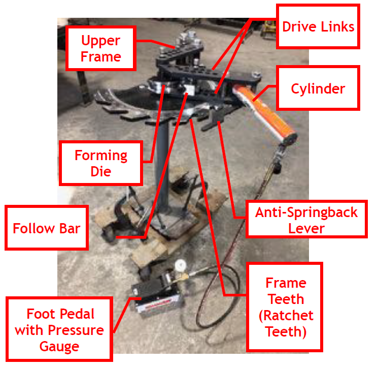
| The tube bender with foot pedal. |
- Die Set consists of 3 Parts:
- One Forming Die
- One Pressure Die (Follow Bar)
- One U-Block (A small square block that retains the workpiece.)
- The Forming Die does not rotate. The Follow Bar rolls around the die. A stationary die makes it easier to control the location of the bend your workpiece.
- Our machine is equipped with a foot pedal control. (The manufacturer’s instructions and the YouTube instructions show a hand control.)
Installation
| |
|---|---|
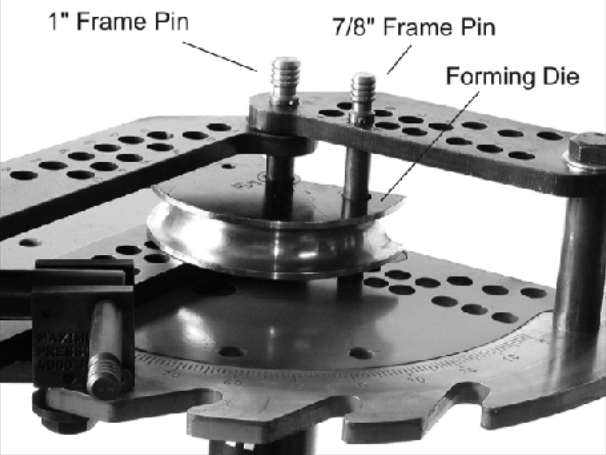
| Setting up the Forming Die |
1. Install the Forming Die.
- Place the Forming Die into the bender with its rounded side forward.
- Insert the 1” Frame Pin
- Rotate the die until the second hole lines up with one of the numbered holes in the frame (#1-4, not a lettered hole)
- Insert a 7/8” Frame Pin (Locking Pin) to prevent the Forming Die from rotating.
2. Install the Pressure Die (Follow Bar)
| |
|---|---|
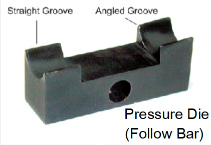
| Detail of the Follow Bar |
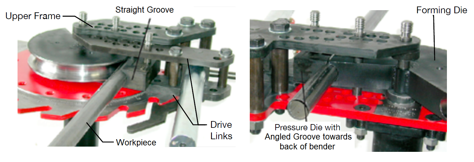
- Rotate the Drive Links counter-clockwise until parallel with the Upper Frame.
- The side with the angled groove MUST be installed with the angled groove facing the back of the machine. If the pressure die is installed with the angled groove facing in the wrong direction, it will try to dig into the workpiece and bend quality will suffer.
- Engraved into the pressure die will be the O.D. size of the tubing or pipe and the hole number that it should be installed into. (The Hole is located on the Drive Links, not the Upper Frame) If the pressure die is placed in a hole number other than the one marked on it, bend quality will suffer.
- If the tube or pipe is flattening a large amount on the outside, check to make sure the pressure die is installed in the correct drive link
| |
|---|---|
| Correct Set-Up of the Workpiece with the Forming Die. |
- Insert the workpiece between the Forming Die and the Pressure Die. Again, Make sure the angled groove on the Pressure Die sits toward the back of the bender. The markings on the Pressure Die will face up.
- Insert a short 7/8" pin through both the drive links and the pressure die using the hole number engraved into the Pressure Die.
3. Install the U-Block
- The top of the upper frame has two rows of 7/8" holes labeled with letters or numbers. The front seven row holes (1,2,3,4,E,F,G) are in a straight line and the back eight holes (A,B,C,D,5,6,7,8) are staggered. The back holes are the ones normally used for the U-Block pin.
- Position the workpiece where you want it bent. Firmly rotate the workpiece counterclockwise. This will seat the workpiece in between the forming die and pressure die, removing any play.
- Install the u-block and a long 7/8" frame pin into one of the 7/8" back side holes AS CLOSE TO THE 1" FRAME PIN AS POSSIBLE. (This is why the workpiece was first pushed counter-clockwise.) It may be helpful to rotate the Drive Links
clockwise slightly to engage a closer hole.
4. Connect the foot petal and hook it up to the Air Compressor.
- Uncap the fitting at the base of the Cylinder and insert foot petal hose. Twist the fitting to engage the threads and tighten the connection.
- Insert the adapter hose into the foot petal and connect the other end to the shop’s air compressor.
