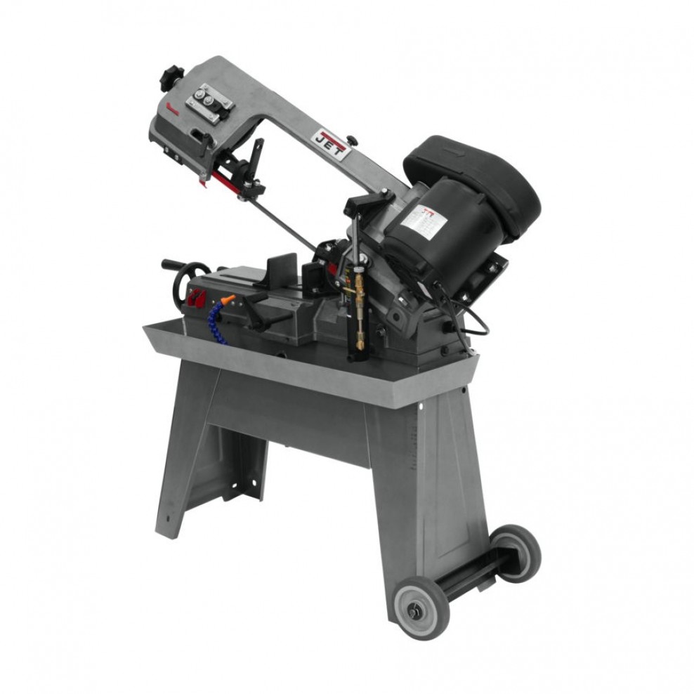
Jet Horizontal Band Saw: Difference between revisions
From Artisans Asylum Wiki
Acharlwood (talk | contribs) m (Added tool restriction) |
Susanvaughn (talk | contribs) No edit summary |
||
| Line 10: | Line 10: | ||
|manual = [https://www.globalindustrial.com/site/images/JET/Manuals/Operating%20Manuals%20PDF/414461-Operating-Instructions-and-Parts-Manual.pdf Operating Manual] | |manual = [https://www.globalindustrial.com/site/images/JET/Manuals/Operating%20Manuals%20PDF/414461-Operating-Instructions-and-Parts-Manual.pdf Operating Manual] | ||
|location = Metal Shop | |location = Metal Shop | ||
|rubric = N/A | |||
|training = [https://www.artisansasylum.com/tool-testing Sign up here] | |training = [https://www.artisansasylum.com/tool-testing Sign up here] | ||
|testing = [https://www.artisansasylum.com/tool-testing Sign up here] | |testing = [https://www.artisansasylum.com/tool-testing Sign up here] | ||
Revision as of 17:48, 23 January 2024
| Jet Horizontal Band Saw | |
|---|---|
| General Info | |
| Make | Jet |
| Model | J-3130 |
| Serial | 414461 |
| Specs | Link to website |
| Manual | Operating Manual |
| Asylum Info | |
| Location | Metal Shop |
| Rubric | N/A |
| Training | Sign up here |
| Testing | Sign up here |
| Restrictions | red |
| Safety First Hazard Analysis |
|---|
|
| Use For | Do Not Use For |
|---|---|
|
|
Basic Operation Instructions
- Perform a safety check prior to use.
- Check blade before cutting for dull or missing teeth.
- Lift the Saw Arm and use the lever on the Hydraulic Control Valve to stop the downward motion of the blade.
- Avoid touching the blade tension knob.
- Securely clamp the workpiece into the Machine’s Vise using the Vise Hand Wheel.
- Workpiece must fill the vise to at least center of the vise in order to be secure.
- Do not risk damage to yourself or the machine by clamping a workpiece insecurely.
- Orient work in the vise to maximize length of blade engagement.
- If the workplace is long, use support to keep the material level with the vise, and plan for the free side of the workpiece to safely fall once the cut is complete.
- If the cut starts on a sharp edge of the workpiece, dull that edge with a file.
- (Optional) to fine tune cut location, use the Travel Speed Dial and the Travel Start / Stop Lever to lower the blade close to (but not touching) the workpiece.
- Flip the Power Switch to start machine.
- Make sure blade is NOT in contact with workpiece prior to starting motor.
- Perform the cut.
- Flip the Travel Start/Stop Lever and let the machine automatically lower the blade into the workpiece. Do not manually lift or press the blade arm during the cut.
- Speed can be adjusted using the Travel Speed Dial. If workpiece smokes at any point during cut, use the Travel Speed Dial to slow the cut speed.
- The machine will turn itself off when the cut is done. (The Auto Shutoff Tab will flip the Power Switch.)
On Angled Cuts
- Use the bolts on the Machine Vise for adjustments. The degree scale for is for quick and approximate adjustments — use a protractor when high accuracy is needed.
