Brackets Tutorial 1: Solidworks From Zero
Link to: Bracketage Main Page
Forward to: Tutorial 2a
Solidworks basic tutorial by Jim Bredt 20240606
Loading Solidworks
This tutorial assumes no prior experience with Solidworks. It will take you through the basic steps for designing a brick with a hole. After this, you will know enough to begin experimenting with the sketch and feature tools, and to move on to the next tutorial.
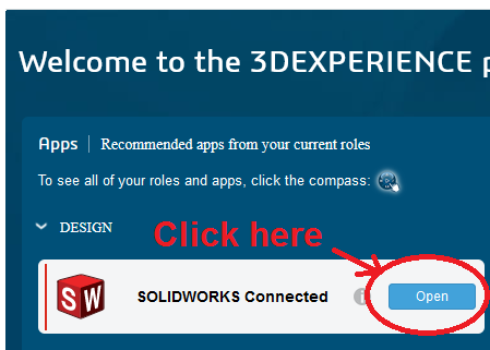
Click on the "Solidworks Connected" icon and you should see the Solidwork splash screen appear. Sometimes you will be asked to supply a username and password. These are on a printed paper taped to the lower left of the computer monitor. Click through whatever sequence of dialog boxes is required to open the application.
Create a Brick
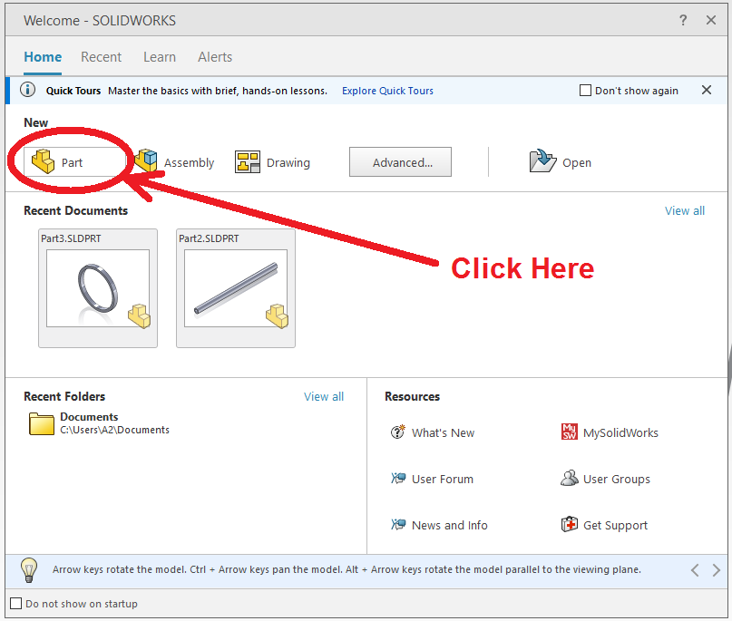
Solidworks takes a minute or two to load. Once it is operating, there will be a "Welcome" window that offers a few options.
Select "Part" to create a new design for a part.
Features Tab
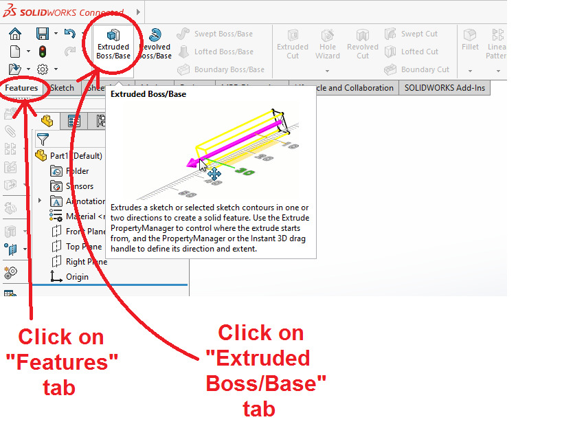
The first operation is to create a brick. In the "Features" tab, select "Extruded Boss/Base." There are other tools under the Features tab including operations such as cutting and revolving, but the simple extrusion operation is what we start with.
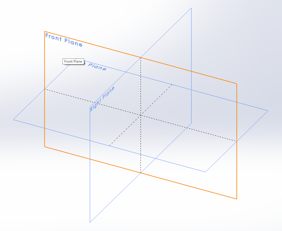
Openinng the Extruded Boss/Base tool will open a view to select a plane for making a 2-D sketch. It doesn't matter which plane you select at this point, click on one of them.
Sketch
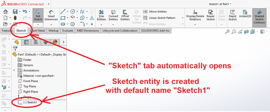
The "Sketch" tab will automatically open and the program will go into a 2-D viewing mode.
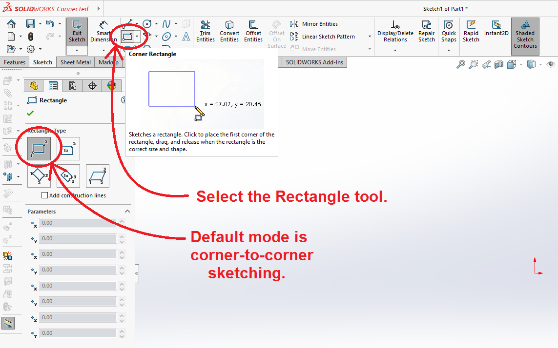
Various sketching tools are available. In this tutorial we will cover a few of them, starting with the Rectangle tool.
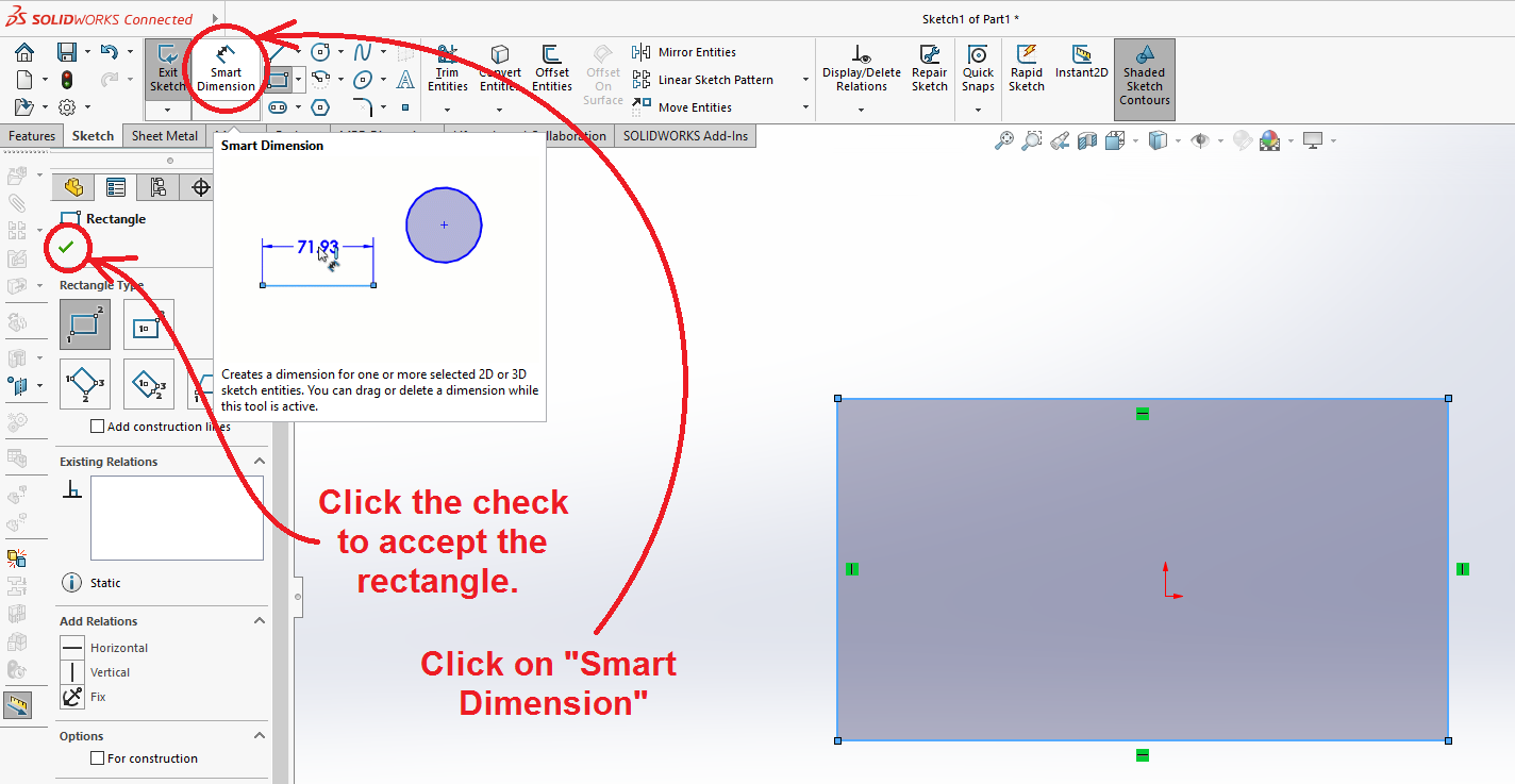
Select the Rectangle Tool from the tool bar.
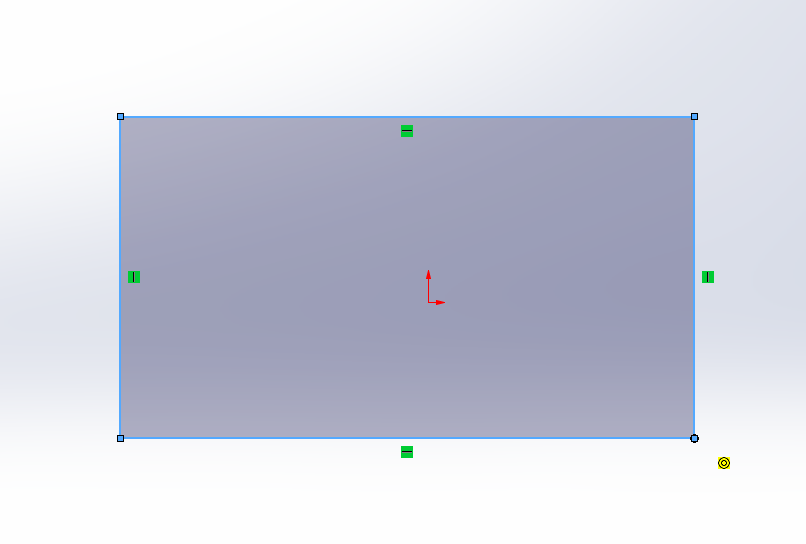
Click and drag the cursor diagonally to sketch a rectangle. Don't worry about how big it is. Click the check mark to accept it.
Smart Dimension
Select the "Smart Dimension" tool from the tool bar.
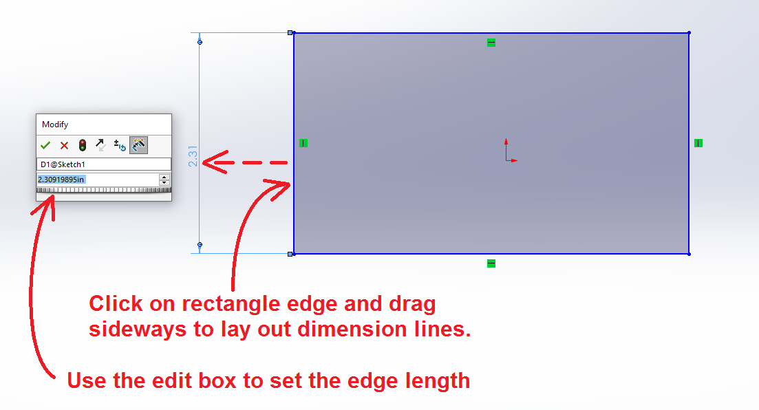
Click the cursor on a side of the rectangle and drag it away from the part. A set of dimensioning lines should appear, along with a dialog box with an edit window. Change the value in the edit box and click the check mark.
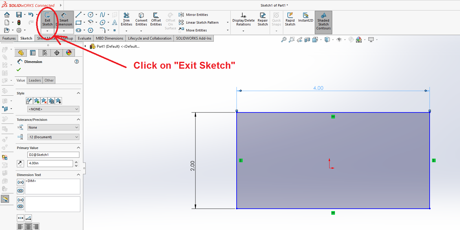
Add dimensions for both the length and width of the rectangle as shown below.
Exit the Sketch
Click on "Exit Sketch."
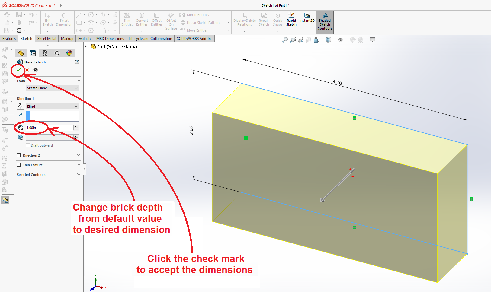
The program will automatically re-open the "Extruded Boss/Base" feature tool. The brick thickness will have some default value. Select the edit box and change its value. Click the check mark to accept the values.
Cut a Hole in the Brick
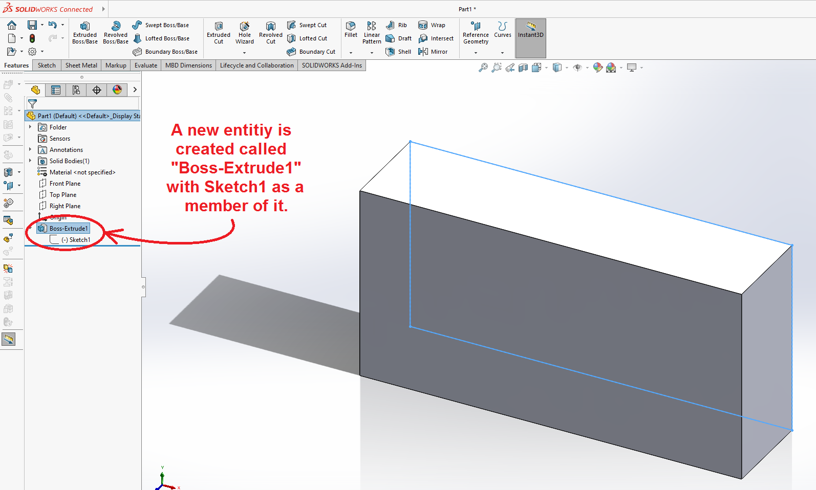
The computer should now display a 3-D rendering of the brick. The features tree will show an entity called "Extrude1". You can select the name and change it if you like.
Sketch on a Face of the Brick
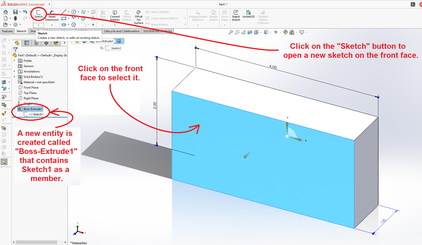
Next we will add a hole to the part design. Click the cursor on one face of the brick to select it. Click on the "Sketch" tool to open a new sketch.
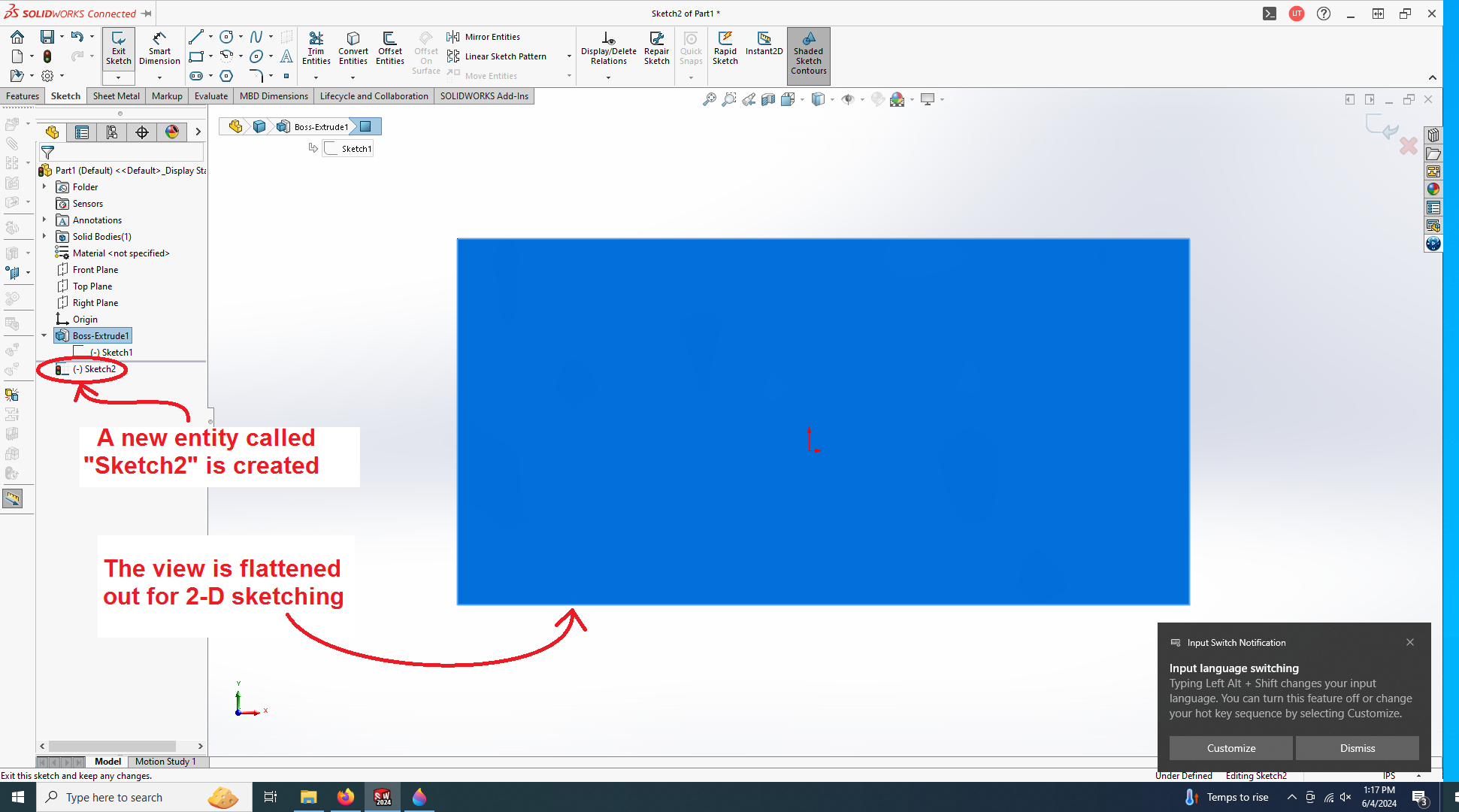
The view will switch to a 2-D view for sketching on the selected plane.
Sketch a Construction Line
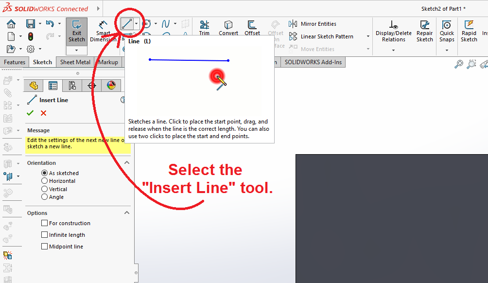
Select the "Insert Line" tool from the tool bar.
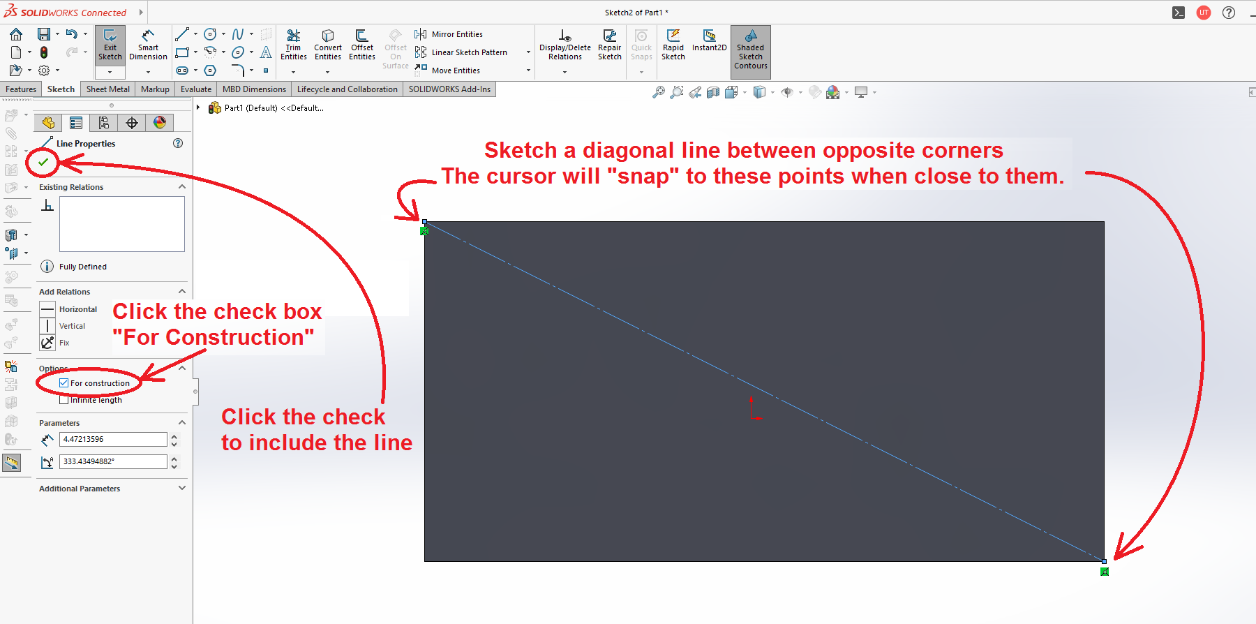
Hover the cursor near to one of the corners of the rectangle. The system should make the cursor "snap" to the corner. Click there and release. A line will appear between the corner and the location of the cursor. Move diagonally down to the opposite corner and click. Move the cursor over and check the box labeled "For Construction." Hit the green check mark to accept.
Sketch a Circle
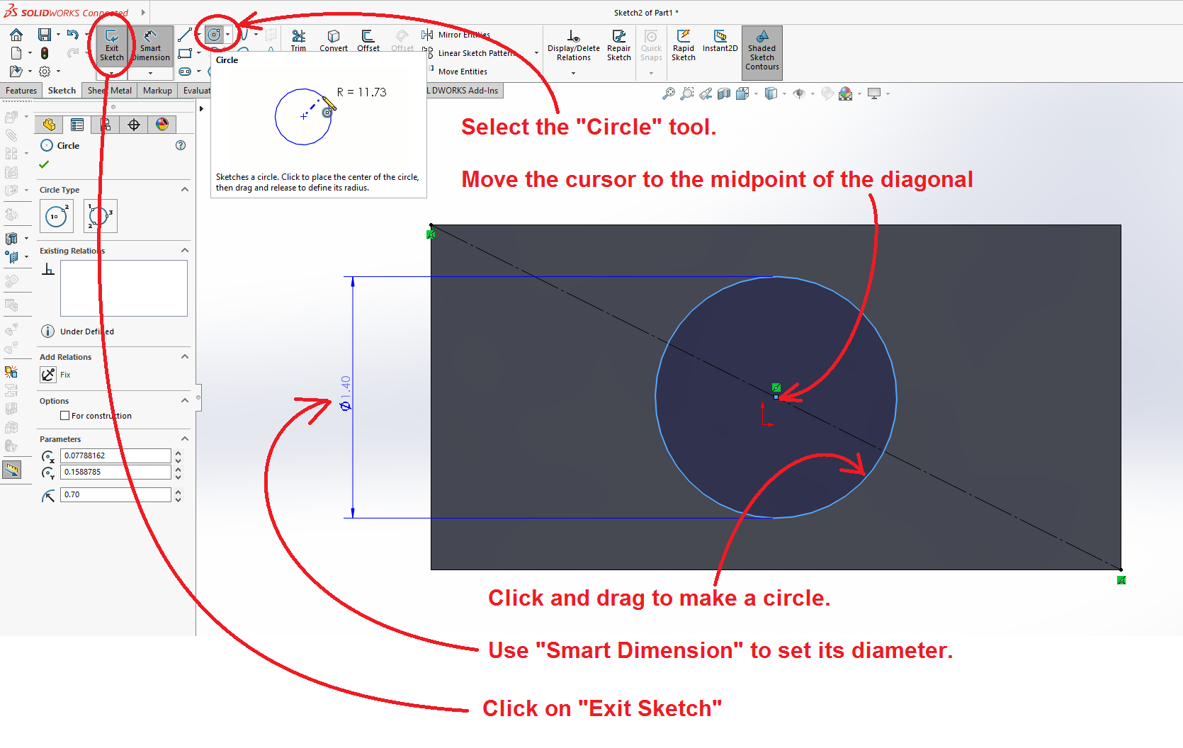
Select the "Circle" tool from the tool bar. Move the cursor near to the midpoint of the diagonal line. Once it is close enough, a small tag should appear that represents the midpoint of the line. Click there and drag the cursor away from the point. Click on "Smart Dimension" and then click on the circle. Drag some dimension lines out to a convenient location and set the value of the circle diameter (or radius) to a desired value.
Click on the green check mark to accept. Hit "Exit Sketch."
The Extruded Cut Tool
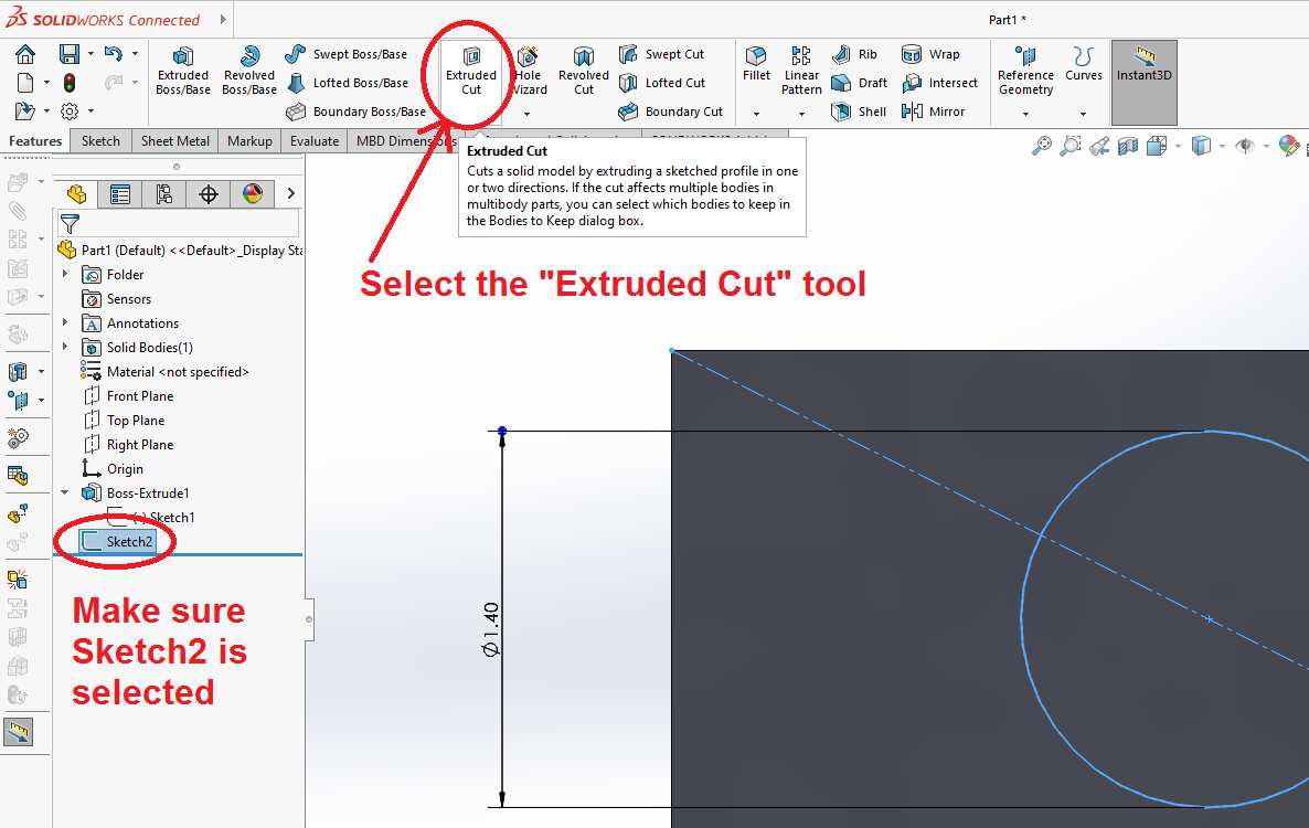
A sketch entity with the default name "Sketch2" should appear at the bottom of the features tree on the left. Click on the name to select this feature and then select the "Features" tab and select "Extruded Cut."
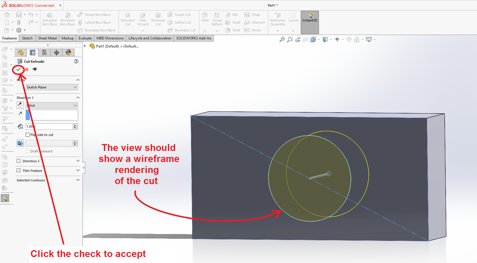
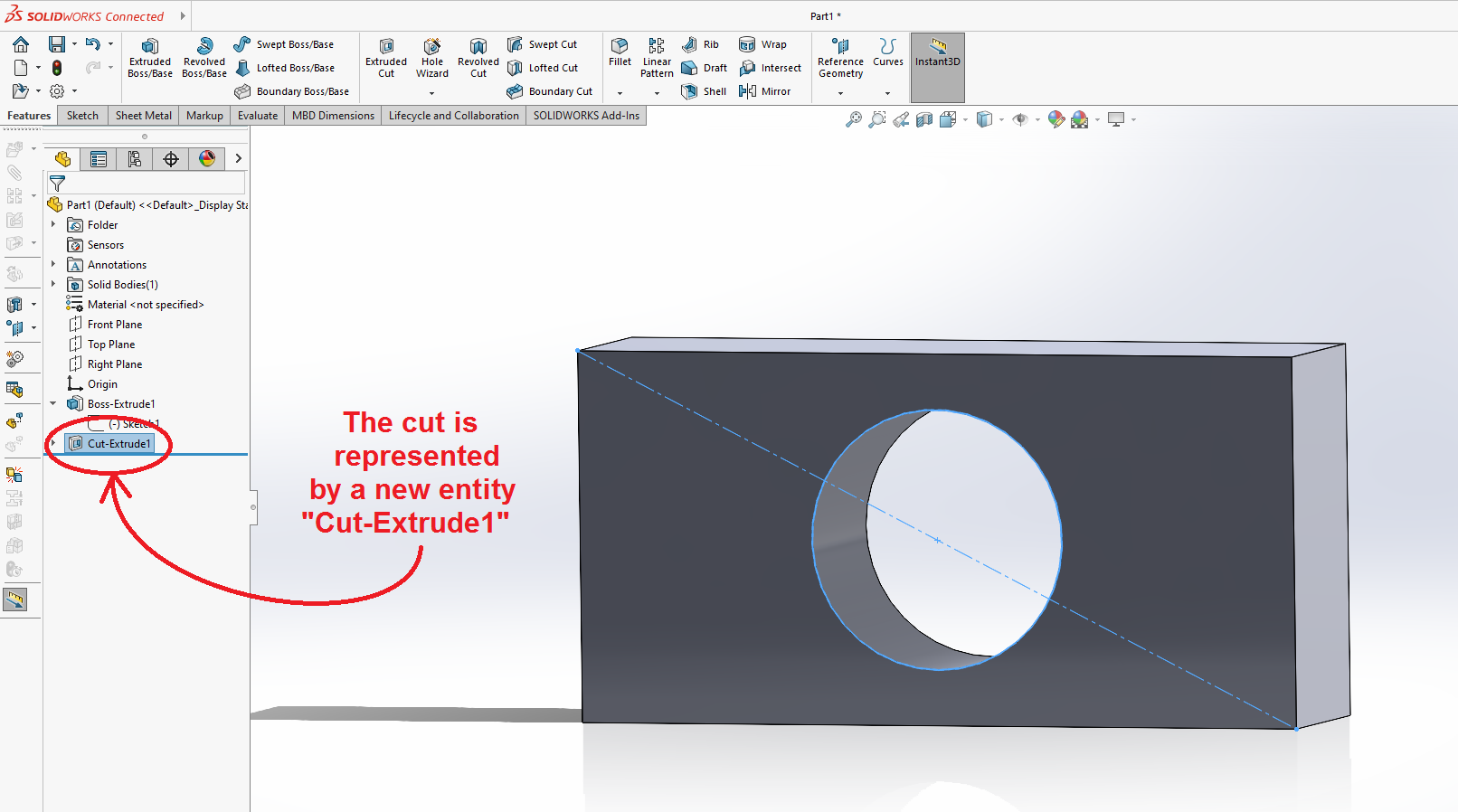
The tool should be able to automatically find the right parameters to cut the hole through the brick. If you wished the hole to only go part way through the brick, you can change the depth dimension for the cut as long as it is in "Blind" cutting mode.
Click on the green check box to accept.
A new feature will appear on the "Features" tree, called "Cut-Extrude1" which represents the cut.
Save the File
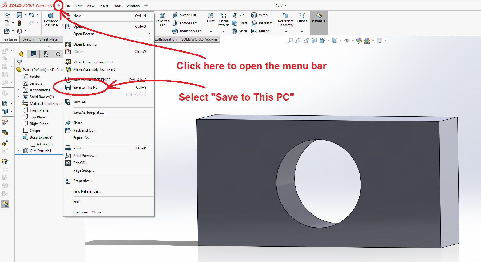
Next we save the file. Click on the (![]() ) small arrowhead next to the Solidworks logo at the top left corner of the window. This will open up a conventional menu bar. Select "File" and the "Save to This PC."
) small arrowhead next to the Solidworks logo at the top left corner of the window. This will open up a conventional menu bar. Select "File" and the "Save to This PC."
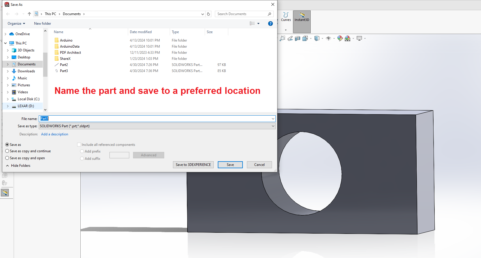
A conventional File::Save dialog will open. Name the part and save it to an appropriate location. It is recommended that you save it to a portable thumb drive so you can carry your work from computer to computer.
Save the part as a "SLDPRT" which is the Solidworks native format. You may also wish to export the file in some other more portable format, such as "DXF".
This concludes the first tutorial.
