Brackets Tutorial 2a: Reverse-Engineering a Bracket in Solidworks
Link to: Bracketage Main Page
Backward to: Tutorial 1
Forward to: Tutorial 2b
Solidworks tutorial by Jim Bredt 20240609
Introduction
This tutorial assumes basic experience with Solidworks. If you are unsure how to use the basic tools in Solidworks, then step through the previous tutorial which assumes no prior experience.
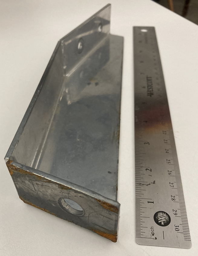
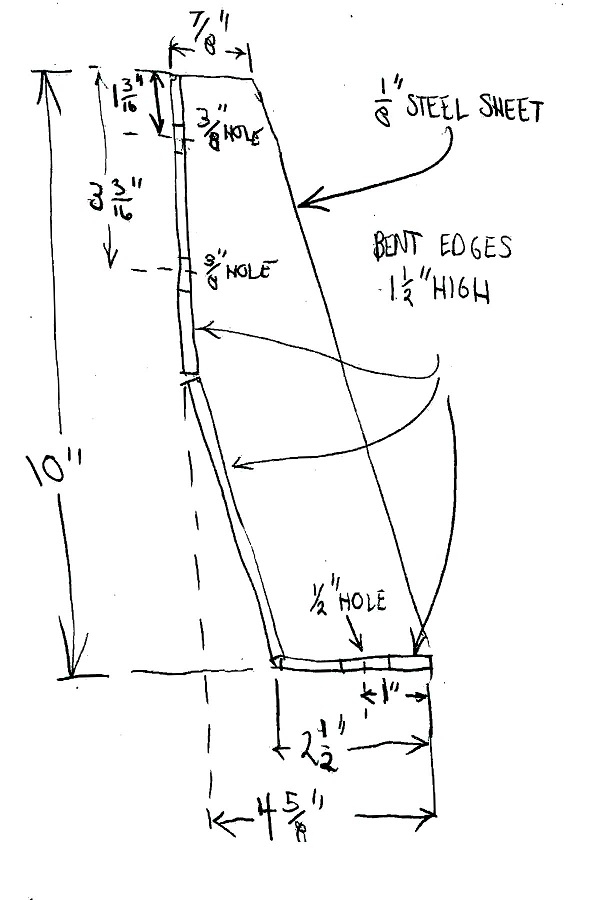
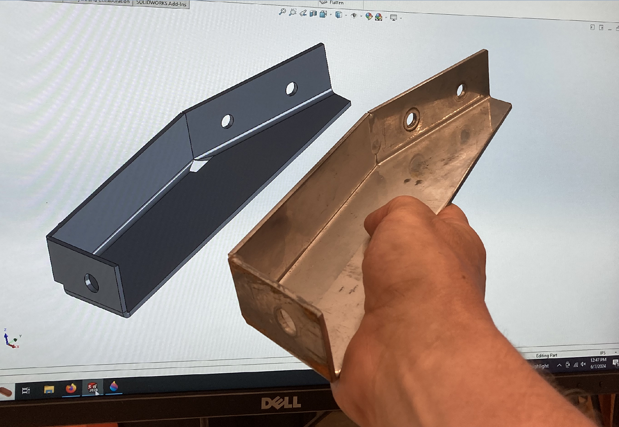
In this tutorial we will create a Solidworks design for an existing steel bracket, shown below left. It is a corner brace from a modular(80/20) metal frame. The dimensions are given below right.
In the following section (Tutorial 2b) we will export the Solidworks data to a CNC plasma cutter and fabricate a replica.
The design strategy is to create a solid brick that conforms to the convex outer contour of the bracket; add holes in the proper locations; and then use the "Convert to Sheet Metal" tool to finish the part.
Change the Units to IPS
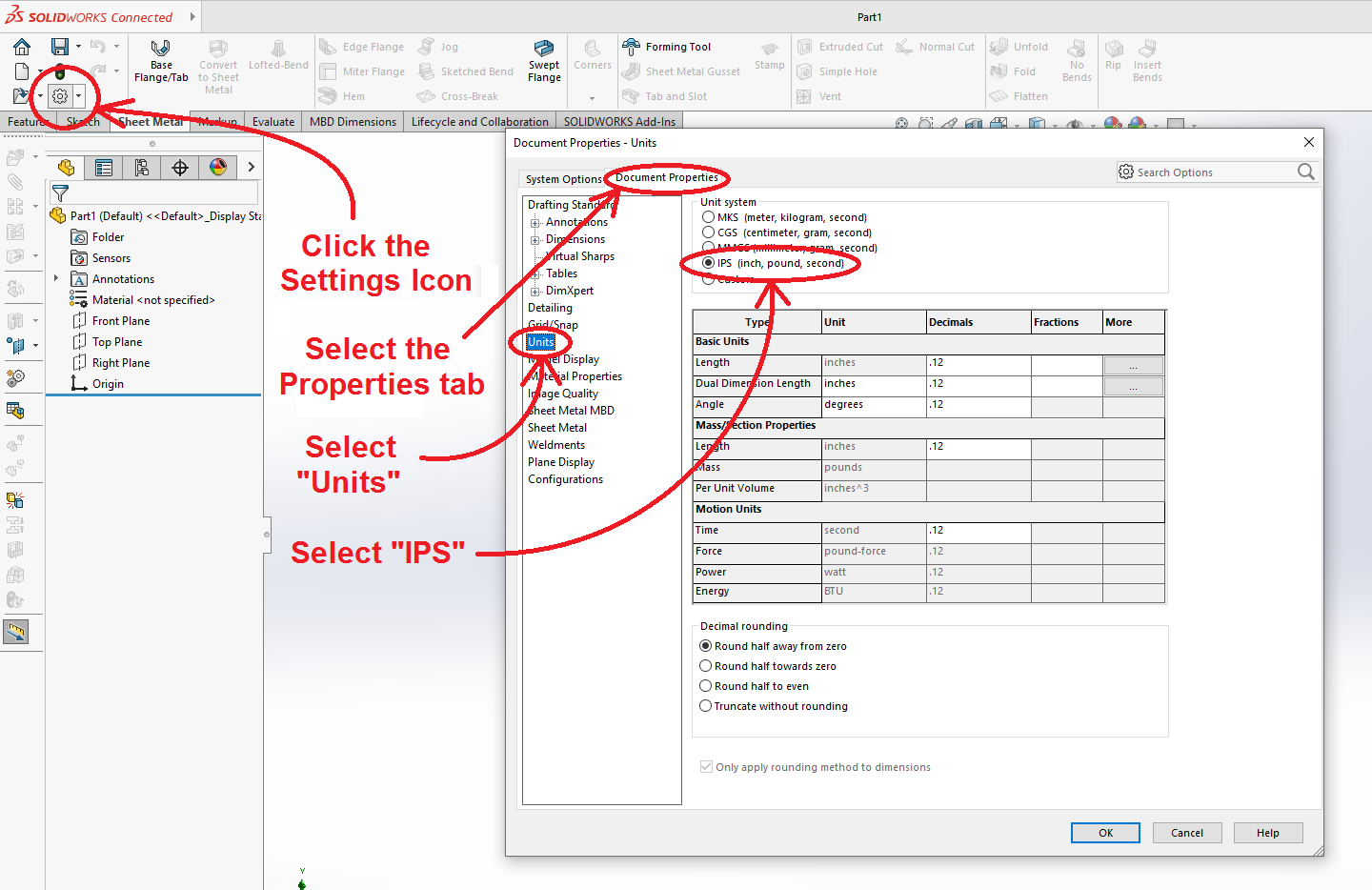
Change the drawing units to inches. Click on the (![]() ) gear icon in the upper left corner of the window. Select the "Document Properties" tab. Make sure the units are set to "IPS" (Inches-Pounds_Seconds). We will be creating data for the Torchmate CNC plasma cutter, and that machine operates in inch units.
) gear icon in the upper left corner of the window. Select the "Document Properties" tab. Make sure the units are set to "IPS" (Inches-Pounds_Seconds). We will be creating data for the Torchmate CNC plasma cutter, and that machine operates in inch units.
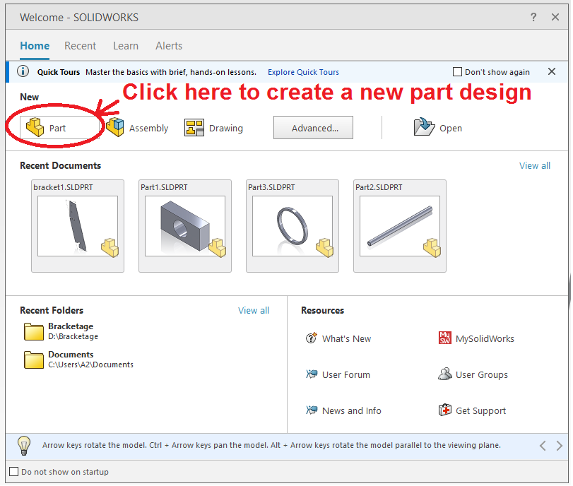
When you load Solidworks you will see a dialog box like the one below.
Select "Part" to create a new design for a part.
Create an Extrusion
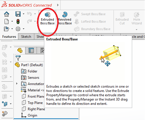
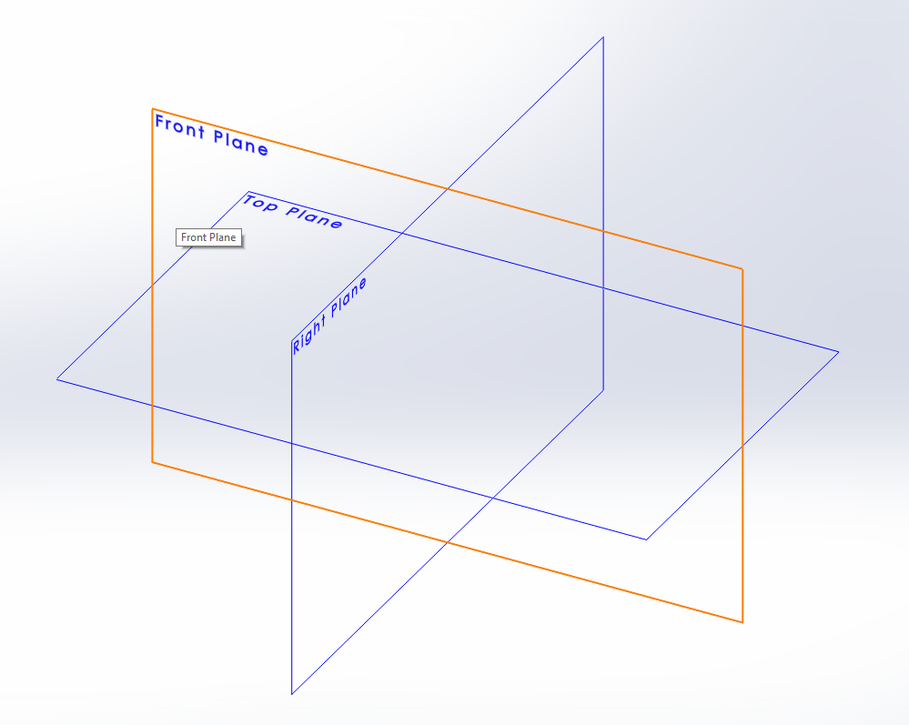
Select "Extruded Boss/Base" in the "Features" tab. Select a plane to sketch on.
Sketch the Outline of the Bracket
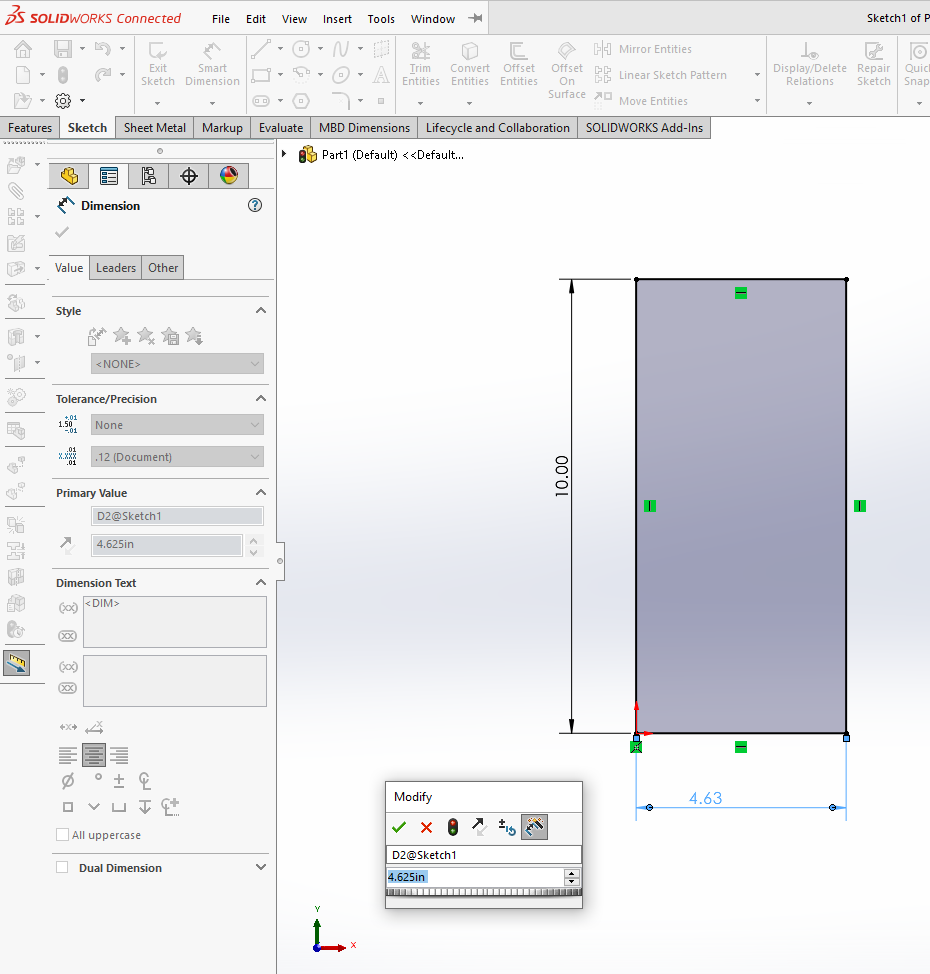
After selecting a sketch plane, a 2-D Sketch window will open. Select the rectangle tool, draw one, and dimension it as shown below left. If you are not sure how to do this please check here. Use Smart Dimension to set the rectangle size.
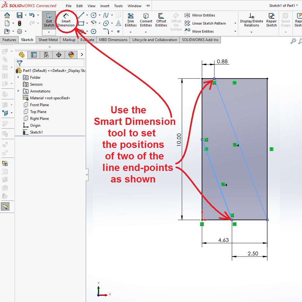
Select the line tool and draw two diagonals as shown below right inside the rectangle. Use Smart Dimension to set the location of the points that are on horizontal rectangle sides. If you are unclear how to use the Line tool, please look here in the first tutorial. These lines should NOT be checked "for construction" as we did in the first tutorial.
Add a Parallel Relation to the Two Lines
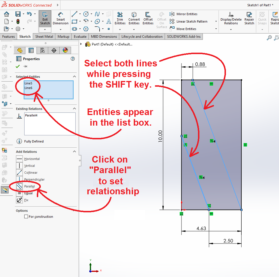
Select both of the new lines by holding down the "SHIFT" key and clicking on both of them. A list box opens up on the left margin of the window that shows common shared properties of both lines. Here you can define them as Parallel. This will make the last of the four endpoints fully defined in its location.
Trim off Extraneous Lines
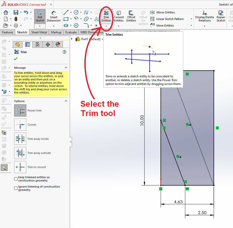
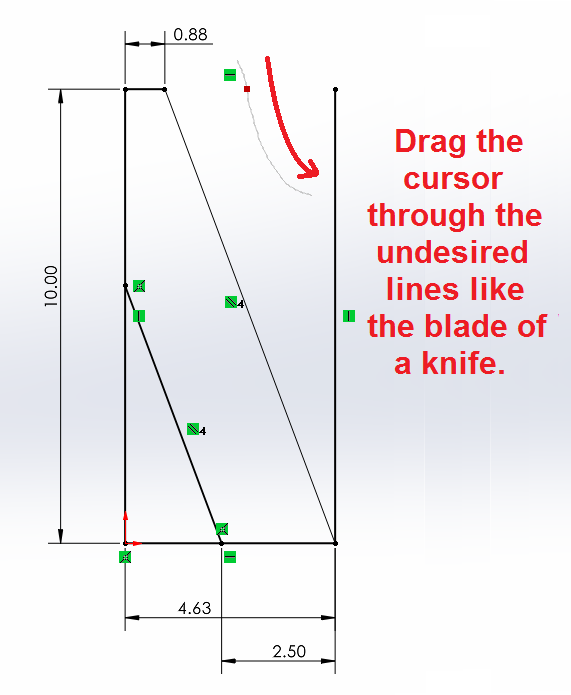
Select the Trim Tool and trim off the extraneous corners of the original rectangle. This tool allows you to eliminate lines by dragging the cursor so it crosses an undesired line, as shown in the figures below.
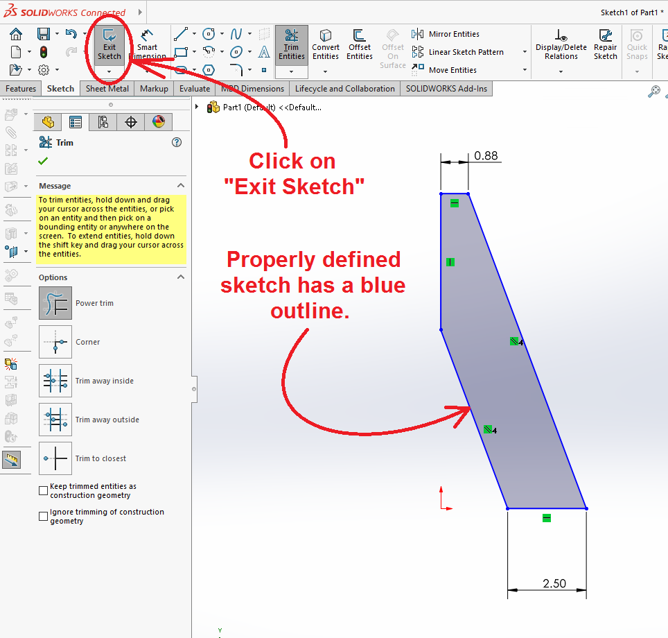
The correct shape is a simple polygon with six sides as shown below right. Click on "Exit Sketch" to accept the design.
Finish the Extrusion
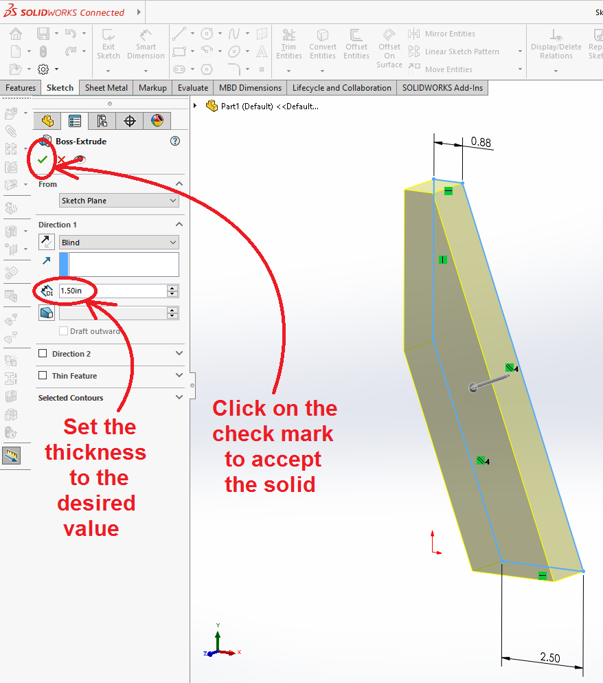
As soon as you exit the sketch, the "Extruded Boss/Base" window opens again to ask for the thickness. For this part the thickness is 1.5 inches. Click on the (![]() ) green check-mark to accept the design.
) green check-mark to accept the design.
Add Holes to the Design
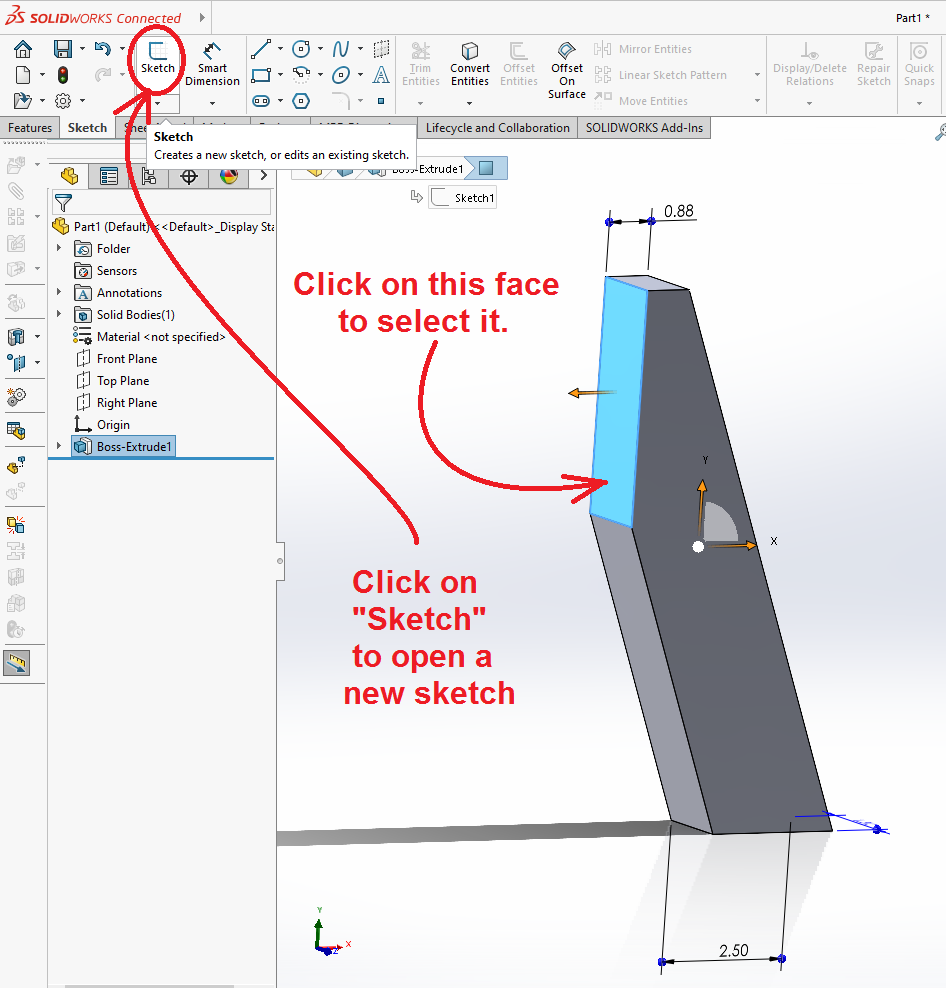
The holes in the bracket are added almost exactly as the hole was created in the first tutorial. Select the vertical face at the tapered end of the brick, as shown below.
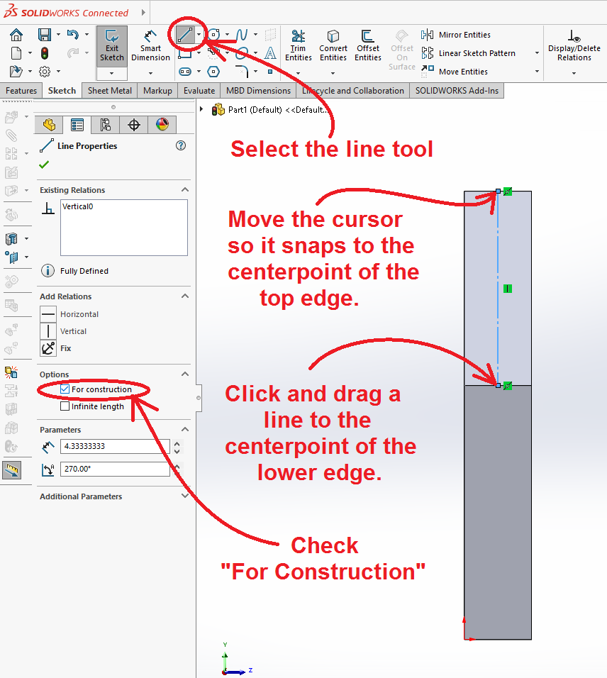
Sketch a line through the center line of this face and select it for construction.
Locate the Hole Centers
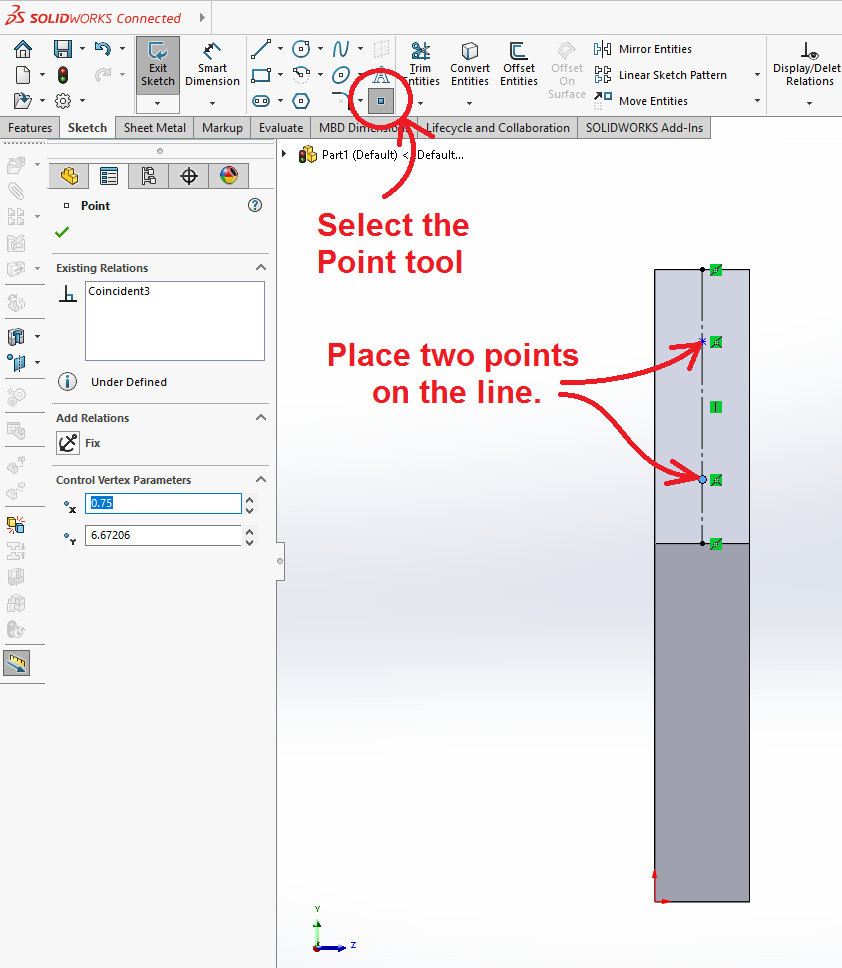
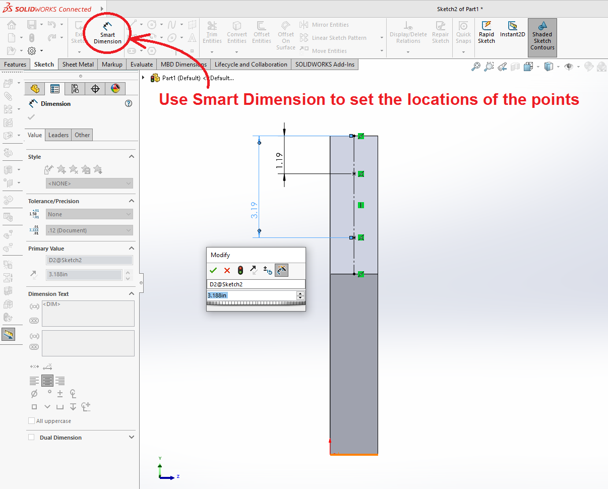
Select the Point tool and add two points along the construction line, spaced out approximately. Select "Smart Dimension" and click the mouse on one of the points and then the top edge of the sketch area. A set of dimension lines should drag out sideways, and an edit box will allow you to type in the correct dimensions, as shown below right.
Use Smart Dimension to set the locations of both points.
Sketch Two Circles
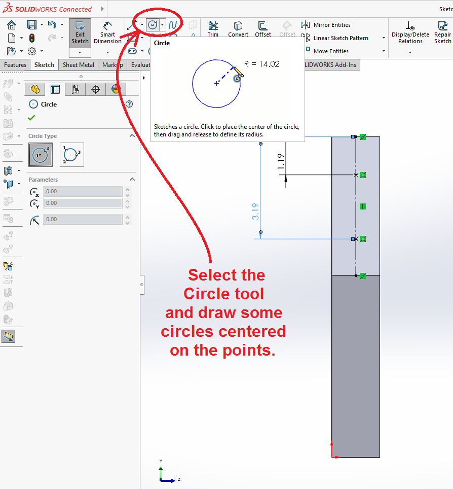
Select the circle tool and draw two circles centered on the two points you just located.
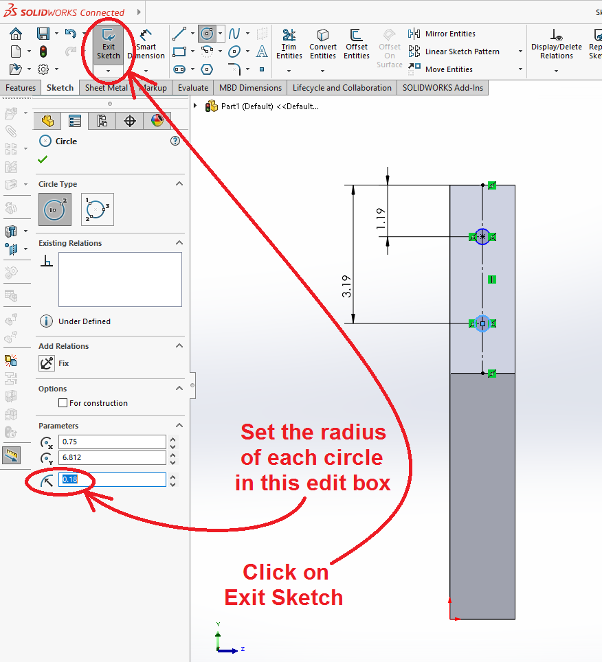
Select each circle separately and type a radius into the edit box as shown. For this part, the holes are supposed to be 3/8" in diameter, so the radius is 0.188. Select "Exit Sketch" after you have done this.
Extruded Cuts
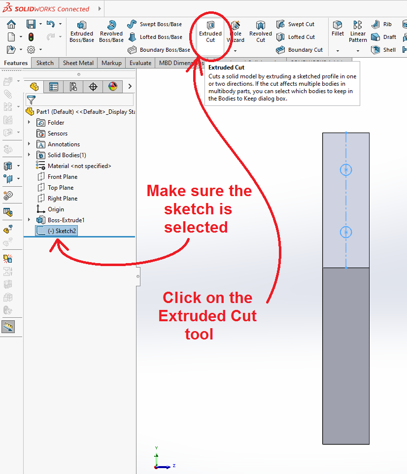
With the sketch selected that you have just closed, open the "Features" tab and select "Extruded Cut".
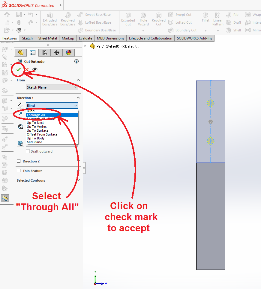
Unlike the first tutorial, open the pull-down menu to select the cutting mode, and select "Through All" This will cause the holes to penetrate the brick no matter what thickness it is.
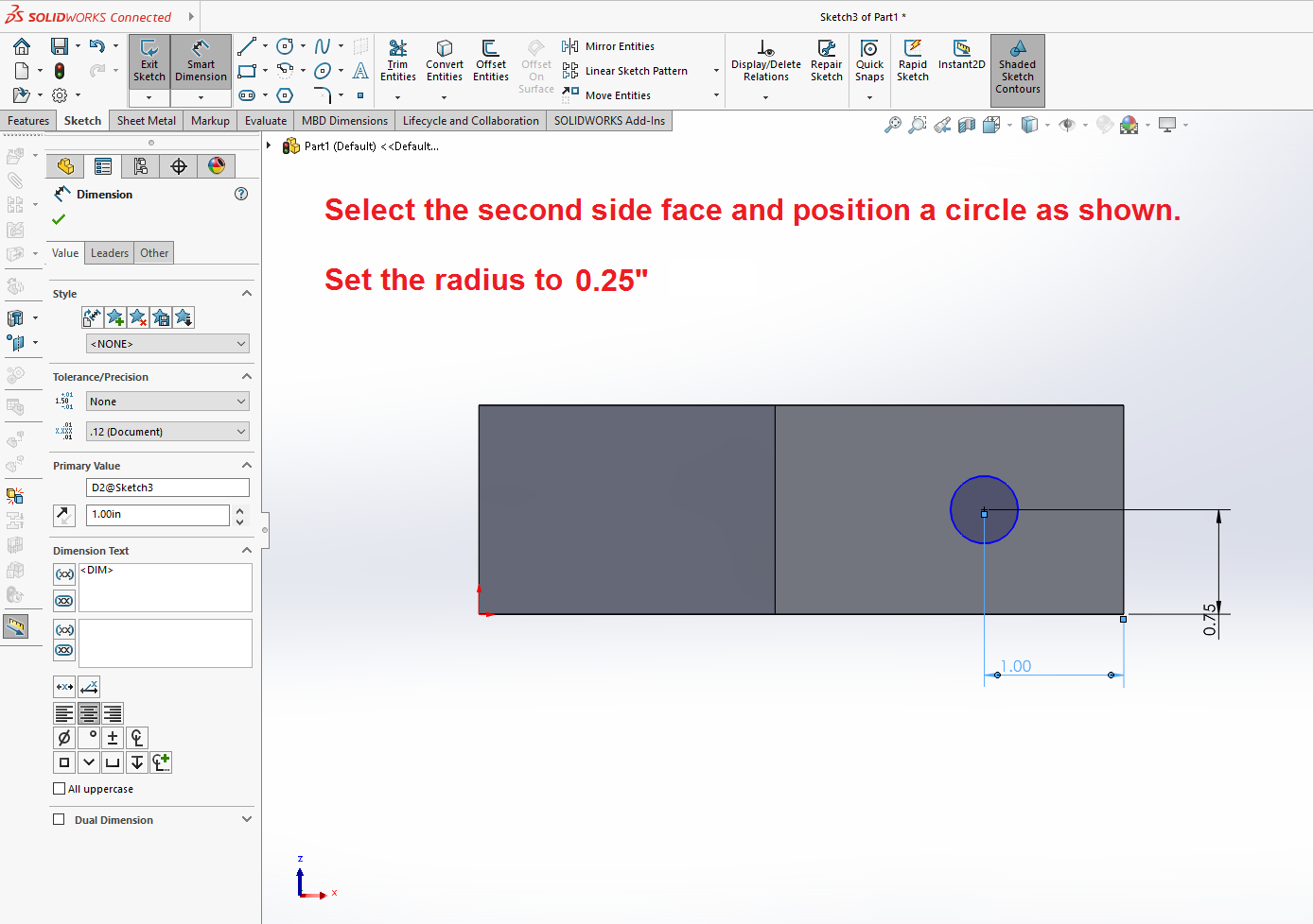
After doing that, repeat the process to design a hole on the lower face of the bracket. Select the face, open a sketch, and sketch a circle as shown below right. The diameter is 0.5" (or 0.25" radius) and it is located 1" from the right edge and 3/4" up from the bottom.
Close the sketch and select "Extruded Cut" again to project the circle in this sketch through the solid.
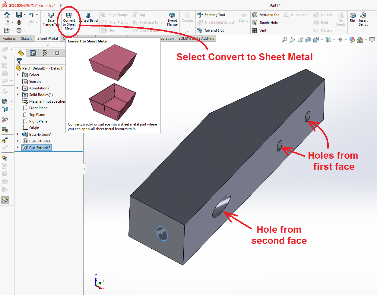
The holes you just cut should be visible on the side face of the brick, as shown below.
Convert to Sheet Metal
Under the "Sheet Metal" tab, select "Convert to Sheet Metal."
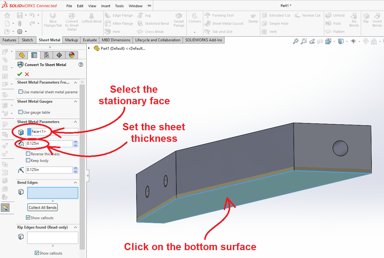
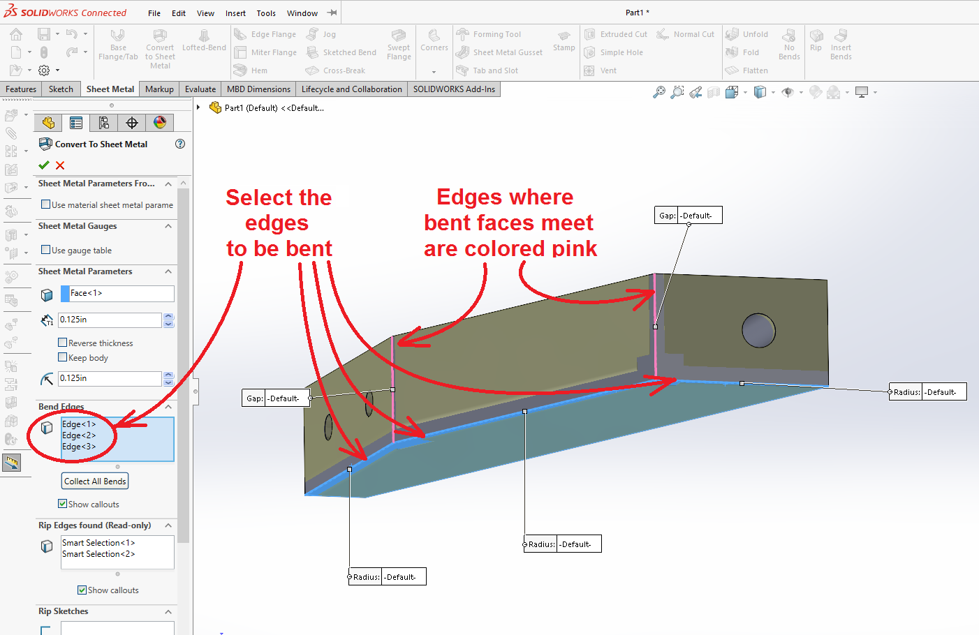
The first operation with this tool is to select a stationary face on the solid. That face is considered the bottom of the shape, and the bent sides are reoriented relative to it. Click the cursor on the bottom face of the brick, as shown below. The sheet thickness for the bracket is 0.125". Set that parameter now.
After the face is selected, click the cursor on the three edges of the brick where bends exist in the bracket. The references should appear in a list box on the left margin.
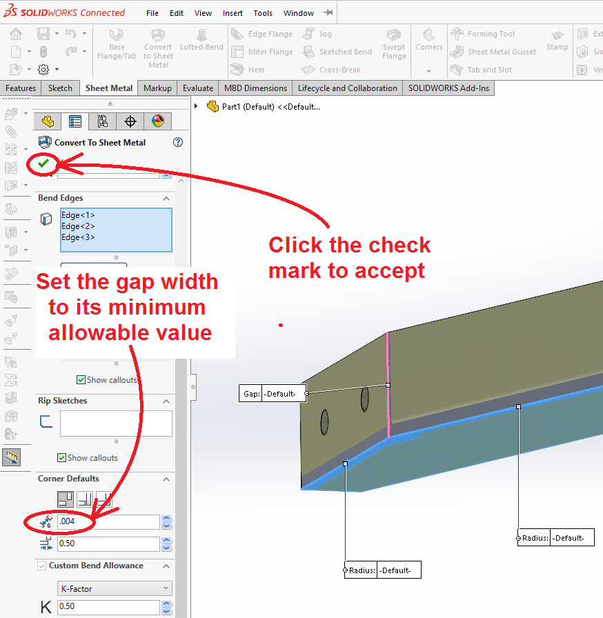
Scroll down in the settings box on the left margin and find the gap width under "Corner Defaults." Set this to the minimum allowable value (0.004"). Click on the (![]() ) green check-mark to accept the design.
) green check-mark to accept the design.
Finished
The design of the bracket is complete. Save your work before proceeding to the next tutorial.
Forward to: Tutorial 2b
