Plasmatron Nozzle Assembly Instructions
Link to: Plasma Shop main page
You may need to widen the window to view the pictures in their optimal configuration
Oveview
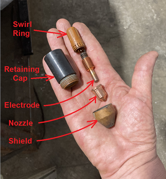
The Torchmate CNC plasma cutter (also known as the Plasmatron) uses a Hypertherm PowerMax85 plasma torch as its cutting tool. The torch is carried on the robot gantry in a vertical orientation. The cutting tip consists of an assembly of five parts. It must be assembled by the user and if it isn't done correctly, the machine will fail to cut or it will cut poorly.
Instructions for how to pick the nozzle and the correct speed and power settings are located here
Exploded views of the nozzle assemblies (with part numbers) taken from the Hypertherm manual are copied for Fine-Cut and Large-format nozzle sets.
The Torch Parts
Nozzles
| |
|---|---|
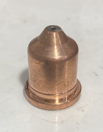
| 45-Amp large format nozzle (copper) |
| |
|---|---|
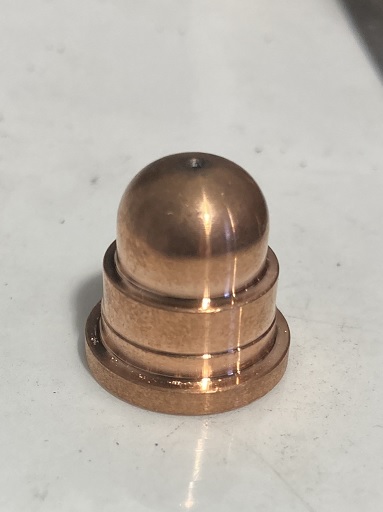
| "Fine-Cut" small format nozzle (copper) |
The part that effects the cutting action is called the nozzle. They are made of copper. There are four alternatives: one small format (called "Fine-Cut) and three in a larger format. The thickness and material of the workpiece determines the choice of the nozzle, and machine settings are set accordingly.
The Fine Cut nozzles have hemispherical tips and they are shorter than the large-format nozzles. They can cut sheets between 0.024" (24-Ga) and 0.134" (10-Ga). These may be run at either 40 or 45-amp depending on the range of thickness.
The three large-format nozzles come in 45-Amp; 65-Amp; and 85-Amp sizes. They have conical tips and they are taller than the Fine-Cut nozzles.
Most often the 45-A nozzle is used. In carbon steel, it is appropriate for sheets 0.060" (16-Ga) up to 1/4-inch thick.
Please note: 45A nozzles may not have any distinguishing marks. 65A and 85A nozzles will always have the current setting inscribed on them.
These components wear out after 1/2 to 1 hour of arc time. Inspect them for wear. If they show excessive burning or if the orifice is asymmetric, it should be replaced.
Retaining Cap
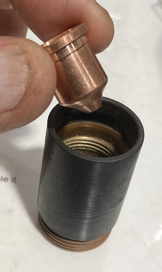
| |
|---|---|
| Inserting the nozzle into the retaining cap. Cap and nozzle inverted. |
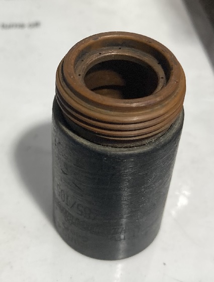
| |
|---|---|
| The torch assembly retaining cap (copper with plastic sheath) |
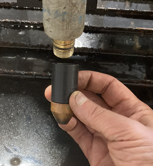
The nozzle retaining cap holds all of the pieces of the assembly in a single package to screw into the barrel of the torch.
Nozzles are inserted into the cap from the open end that doesn't have the copper male thread on the outside. The nozzles rest of a step inside the hollow space in the cap and stick out through the bottom (threaded end) of the cap.
Electrode and Swirl Ring
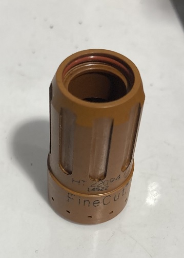
| |
|---|---|
| Swirl ring (plastic). Part shown is right-side-up for a Fine-Cut nozzle, with a single row of holes on the bottom circumference. |
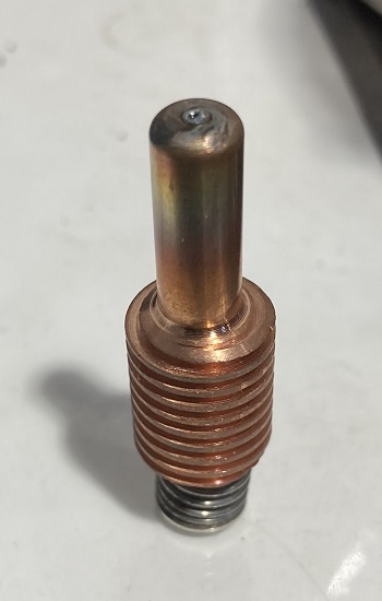
| |
|---|---|
| The torch electrode (copper). One size fits all. The tip visible normally points down. |
The remaining pieces in the nozzle assembly are the Electrode and Swirl Ring.
As you might guess, the Electrode is the source of the plasma arc that does the cutting. It has a plated tip that emits the arc, which faces down when in use. Electrical contact is made by a spring-loaded contact that faces upward into the barrel of the torch. Cooling fins are distinctive features in the middle of the electrode.
Please note: The electrodes should be inspected for wear and set aside if they show large or asymmetric burn marks. If you decide to melt them for copper scrap, you should pry off the spring and spring-loaded upper contact prior to melting.
The Swirl Ring directs the gas flow through the torch barrel past the electrode to the nozzle. This component applies a vortical motion to the airflow so that the torch tends to cut better on one side of the kerf. The pattern is referred to a as "climbing" cut. Solid shapes cut better if the torch moves around the contour CLOCKWISE and holes are cut better if the torch moves around COUNTER-CLOCKWISE.
Assembling the Electrode and Swirl Ring
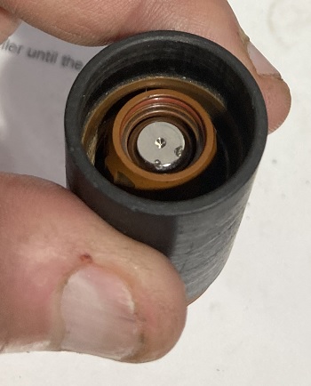
| |
|---|---|
| Top view of the completed nozzle assembly. The electrode is nested inside the swirl ring. Visible are the contact pad on the electrode and the tapered end of the swirl ring. |
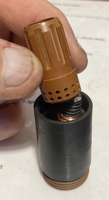
| |
|---|---|
| The swirl ring inserts over the electrode with the tapered end pointing up. Shown is the part for the large-format nozzles (with two rows of holes on the lower circumference.) |
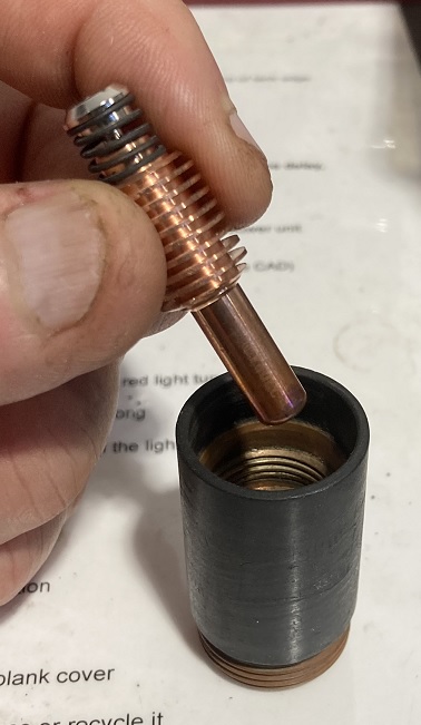
| |
|---|---|
| The torch electrode inserts into the cap after placing the nozzle. |
The electrode is inserted into the retaining cap and seats within the hollow space inside the nozzle.
The swirl ring is inserted last, and the body of the electrode nests inside it. The tapered end of the swirl ring is responsible for making a gas-tight seal to the barrel of the torch, and so it needs to face UP.
Looking from the top, the completed assembly has the electrode nested inside the hollow space of the swirl ring, with the upper surfaces of both components recessed slightly into the retaining cap.
The Shield
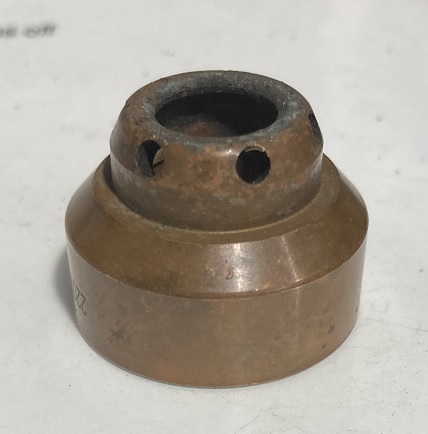
| |
|---|---|
| Shield for the Fine-Cut nozzles (copper.) |
| |
|---|---|
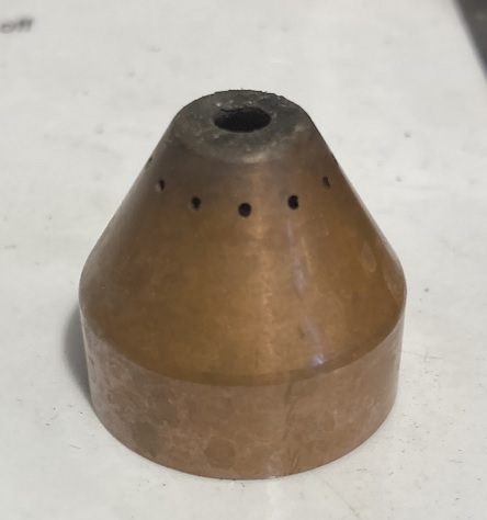
| Shield for the large-format nozzles (copper.) |
| |
|---|---|
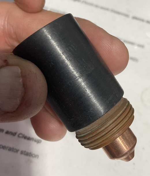
| The nozzle assembly viewed from the side without a shield. Shown with a 45A large-format nozzle. |
At Artisans Asylum we run the torch with shielded nozzles to protect the other components of the assembly. Shields screw onto the copper thread on the bottom of the retaining cap.
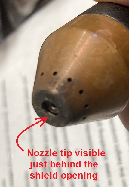
Large-format shields are conical in shape and are taller than the fine-cut nozzles to accommodate the greater height of the large-format nozzles.
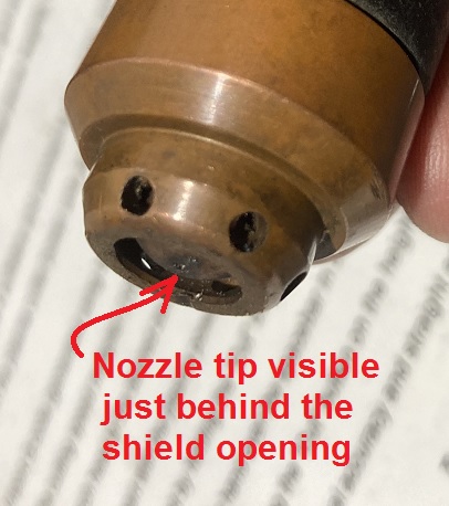
Fine-cut shields are snubbed off with a larger diameter opening to accommodate the blunt, hemispherical Fine-Cut nozzles.
You must use the right size of shield for the nozzle type you choose to cut with. If you select the wrong shield for the job the nozzle assembly won't attach properly to the torch barrel, and the torch power supply may throw an error or not. In either case it will fail to cut nicely or fail to cut at all.
| |
|---|---|
| The Fine-Cut shielded nozzle with the nozzle tip visible about 1/16" inside the shield opening. |
| |
|---|---|
| The large-format shielded nozzle with the nozzle tip visible about 1/16" inside the shield opening. |
When the nozzles are assembled with the correct shield in place, the nozzle tip should be visible about 1/16" (1.5 mm) behind the rim of the shield. If this is not the case, you are using the wrong shield for the job. The torch will cut poorly or not at all if the parts are improperly assembled.
Install the Assembly Onto the Torch Barrel
Congratulations! You have now assembled the nozzle package for cutting with the Plasmatron. A similar nozzle package is also used in the hand-held plasma cutters.
Here's all you need to do to install the nozzle:
- Remove the orange protection cap from the torch barrel.
- Screw the nozzle assembly onto the barrel.
- The thread is right-handed but it's upside-down. You need to turn it COUNTER-CLOCKWISE in order to tighten it.
- Don't overtighten. Just finger-tight is all that is necessary.
- If the torch power supply is on when you do this, it will enter error-state 0-50. To clear the error, turn the torch power off and then turn it back on.
