Brackets Tutorial 3: No Frills Shelf Bracket: Difference between revisions
| (63 intermediate revisions by the same user not shown) | |||
| Line 15: | Line 15: | ||
Insert the bar and line up the cut line with the blade of the Ironworker shear. | Insert the bar and line up the cut line with the blade of the Ironworker shear. | ||
[[File:Tut3_Bracket_nofrills_marking_the_blank.jpg| | [[File:Tut3_Bracket_nofrills_marking_the_blank.jpg|670px|marking]] | ||
[[File: | [[File:SW_gear_icon_tiny.png|6px|thin strip]] | ||
[[File:SW_gear_icon_tiny.png| | [[File:SW_gear_icon_tiny.png|6px|thin strip]] | ||
[[File:Tut3_Bracket_nofrills_setting_blank_in_IW.jpg|220px|bar_in_shear]] | |||
Tigthen down the stock clamp. Depress the foot pedal on the Ironworker to bring the shear blade down. | Tigthen down the stock clamp. Depress the foot pedal on the Ironworker to bring the shear blade down. | ||
'''Release the foot pedal as soon as the bar is cut!''' DO NOT allow the Ironworker to bottom out! | |||
[[File:Tut3_Bracket_nofrills_clamping_stock_in_IW.jpg|250px|clamp]] | [[File:Tut3_Bracket_nofrills_clamping_stock_in_IW.jpg|250px|clamp]] | ||
[[File:SW_gear_icon_tiny.png|10px|thin strip]] | |||
[[File:Tut3_Bracket_nofrills_IW_foot_pedal.jpg|350px|foot]] | [[File:Tut3_Bracket_nofrills_IW_foot_pedal.jpg|350px|foot]] | ||
[[File:SW_gear_icon_tiny.png|10px|thin strip]] | |||
[[File:Tut3_Bracket_nofrills_cut_bar.jpg|220px|cut bar]] | [[File:Tut3_Bracket_nofrills_cut_bar.jpg|220px|cut bar]] | ||
| Line 28: | Line 33: | ||
Now we punch the mounting holes in the blank. | Now we punch the mounting holes in the blank. | ||
Turn off the power to the Ironworker. | |||
Select the punch and die set for 1/4" holes. Note that the die for 1/4" holes is 1/32" larger in diameter: 9/32". Tools for tightening the punch and die are provided in the tool box. | Select the punch and die set for 1/4" holes. Note that the die for 1/4" holes is 1/32" larger in diameter: 9/32". Tools for tightening the punch and die are provided in the tool box. | ||
[[File:Tut3_Bracket_nofrills_IW_punch_die_set.jpg|400px | [[File:Tut3_Bracket_nofrills_IW_punch_die_set.jpg|400px|punch set]] | ||
[[File: | [[File:SW_gear_icon_tiny.png|10px|thin strip]] | ||
[[File: | [[File:Tut3_Bracket_nofrills_IW_tool_set.jpg|380px|tool set]] | ||
Place the die in the die seat on the punch table with the small hole facing up. Tighten with the hex wrench provided. | Place the die in the die seat on the punch table with the small hole facing up. Tighten with the hex wrench provided. | ||
| Line 40: | Line 47: | ||
[[File:Tut3_Bracket_nofrills_IW_die_install.jpg|250px|die drop]] | [[File:Tut3_Bracket_nofrills_IW_die_install.jpg|250px|die drop]] | ||
[[File:SW_gear_icon_tiny.png|10px|thin strip]] | |||
[[File:Tut3_Bracket_nofrills_IW_die_tighten.jpg|300px|die tighten]] | [[File:Tut3_Bracket_nofrills_IW_die_tighten.jpg|300px|die tighten]] | ||
[[File:Tut3_Bracket_nofrills_IW_punch_install.jpg| | [[File:SW_gear_icon_tiny.png|10px|thin strip]] | ||
[[File:Tut3_Bracket_nofrills_IW_punch_install.jpg|240px|punch install]] | |||
Grab the handle at the top of the punch spindle and pull it down to lower the punch into the die. | Grab the handle at the top of the punch spindle and pull it down to lower the punch into the die. | ||
| Line 49: | Line 58: | ||
Tighten the punch with the wrench provided and then return the handle to its top position. | Tighten the punch with the wrench provided and then return the handle to its top position. | ||
[[File:Tut3_Bracket_nofrills_lowering_the_punch.jpg| | [[File:Tut3_Bracket_nofrills_lowering_the_punch.jpg|180px|lower punch]] | ||
[[File:Tut3_Bracket_nofrills_center_the_punch.jpg| | [[File:SW_gear_icon_tiny.png|10px|thin strip]] | ||
[[File:Tut3_Bracket_nofrills_tighten_the_punch.jpg| | [[File:Tut3_Bracket_nofrills_center_the_punch.jpg|240px|punch center]] | ||
[[File:SW_gear_icon_tiny.png|10px|thin strip]] | |||
[[File:Tut3_Bracket_nofrills_tighten_the_punch.jpg|370px|tighten punch]] | |||
Swing the upper part of the stripper into position. | |||
Place the lower part of the stripper underneath it. | |||
[[File:Tut3_Bracket_nofrills_set_the_stripper_1.jpg|390px|stripper 1]] | |||
[[File:SW_gear_icon_tiny.png|10px|thin strip]] | |||
[[File:Tut3_Bracket_nofrills_set_the_stripper_2.jpg|250px|stripper 2]] | |||
Place the workpiece under the stripper and lower the punch to line it up with the mark. Return the release handle to the top position. | |||
Depress the foot pedal to bring the punch down. | |||
'''Release the foot pedal as soon as the hole is punched!''' DO NOT allow the Ironworker to bottom out! | |||
Repeat the process until all of the holes are punched. | |||
[[File:Tut3_Bracket_nofrills_line_up_workpiece.jpg|350px|align with mark]] | |||
[[File:SW_gear_icon_tiny.png|10px|thin strip]] | |||
[[File:Tut3_Bracket_nofrills_blank_punched.jpg|250px|punched workpiece]] | |||
=Bend the Bracket= | |||
This operation uses the [[Hydraulic Shop Press]] that can be found in the back of the shop near the chop saws. | |||
Place the workpiece in the bending tool and lower the tool until it lightly presses against the workpiece. | |||
Square up the workpiece in the tool and make sure the bend mark is under the tool. | |||
[[File:Tut3_Bracket_nofrills_place_blank_in_bending_tool.jpg|238px|blank in bender]] | |||
[[File:SW_gear_icon_tiny.png|10px|thin strip]] | |||
[[File:Tut3_Bracket_nofrills_square_blank_in_bending_press.jpg|240px|square blank]] | |||
[[File:SW_gear_icon_tiny.png|10px|thin strip]] | |||
[[File:Tut3_Bracket_nofrills_pump_bending_press.jpg|242px|pump press]] | |||
Pump the press and bend the workpiece. Check the angle periodically to make sure it comes out with a right angle. | |||
[[File:Tut3_Bracket_nofrills_bending.jpg|238px|bending]] | |||
[[File:SW_gear_icon_tiny.png|10px|thin strip]] | |||
[[File:Tut3_Bracket_nofrills_shop_press_pressure_release.jpg|240px|pressure release]] | |||
[[File:SW_gear_icon_tiny.png|10px|thin strip]] | |||
[[File:Tut3_Bracket_nofrills_bent_bracket.jpg|220px|bent bracket]] | |||
=Cut and Weld the Diagonal Brace= | |||
To strengthen the bracket, we add a diagonal brace to the bracket. First we cut it on the Ironworker. | |||
You can measure it, or you can place the bent piece on a piece of bar stock (in this case, 1/2" x 1/8") and mark it. Try to account for the width of the pen tip. | |||
You can insert bar stock at an angle into the Ironworker. Clamp as normal and chop. | |||
[[File:Tut3_Bracket_nofrills_mark_diagonal.jpg|240px|mark angle]] | |||
[[File:SW_gear_icon_tiny.png|5px|thin strip]] | |||
[[File:SW_gear_icon_tiny.png|5px|thin strip]] | |||
[[File:Tut3_Bracket_nofrills_cut_diagonal.jpg|200px|cut angle]] | |||
[[File:SW_gear_icon_tiny.png|5px|thin strip]] | |||
[[File:SW_gear_icon_tiny.png|5px|thin strip]] | |||
[[File:Tut3_Bracket_nofrills_diag_assembled.jpg|330px|bracket assem]] | |||
Assemble the angle brace to the bracket on the welding bench. As shown it is held up with welding magnets. | |||
Weld the brace to the bracket with a MIG welder. | |||
The [[:Category:MIG Welders | MIG welder]] is a <span style="color:red">RED</span> tool. You must be trained and tool-tested in order to use this tool. | |||
[[File:Tut3_Bracket_nofrills_MIG_welding.jpg|550px|welding]] | |||
[[File:SW_gear_icon_tiny.png|5px|thin strip]] | |||
[[File:SW_gear_icon_tiny.png|5px|thin strip]] | |||
[[File:Tut3_Bracket_nofrills_bracket_welded.jpg|250px|bent bracket]] | |||
=Cleaning= | |||
Before finishing the bracket, we will use the [[Cyclone_Sand_Blaster | sand blaster]] to clean off oxide and slag residue from the welding process. | |||
This is a <span style="color:red">RED</span> tool. You must be trained and tool-tested in order to use this tool. | |||
Before working in either the sand-blaster room or the powder-coating room, you '''MUST''' don goggles and a dust mask. | |||
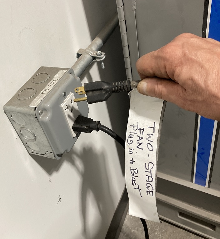
Plug in the two-stage dust collector located in the back of the sand-blaster room. | |||
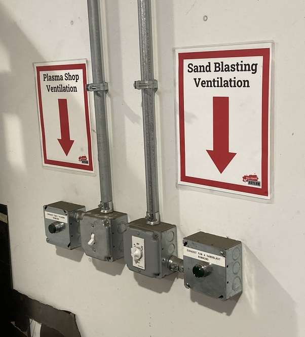
Also switch on the room ventilation fan located adjacent to the CNC plasma cutter. | |||
[[File:Tut3_Bracket_nofrills_powder_ppe.jpg|300px|PPE selfie]] | |||
[[File:SW_gear_icon_tiny.png|5px|thin strip]] | |||
[[File:SW_gear_icon_tiny.png|5px|thin strip]] | |||
[[File:Tut3_Bracket_nofrills_blaster_DC.jpg|220px|sandblast DC]] | |||
[[File:SW_gear_icon_tiny.png|5px|thin strip]] | |||
[[File:SW_gear_icon_tiny.png|5px|thin strip]] | |||
[[File:Sandblaster vent switch.jpg|220px|sandblast vent switch]] | |||
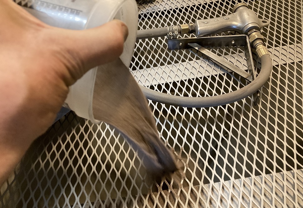
IF the hopper is empty, add media to the cabinet. Don't add too much. There should only be about 2 quarts of media in the hopper. | |||
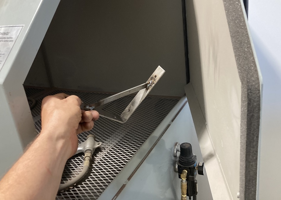
Place the workpiece into the sand-blaster cabinet and seal the door shut. | |||
To blast, point the gun at the workpiece and depress the foot pedal. | |||
[[File:Tut3_Bracket_nofrills_blaster_media.jpg|260px|add media]] | |||
[[File:SW_gear_icon_tiny.png|5px|thin strip]] | |||
[[File:SW_gear_icon_tiny.png|5px|thin strip]] | |||
[[File:Tut3_Bracket_nofrills_blaster_hatch.jpg|250px|blaster hatch]] | |||
[[File:SW_gear_icon_tiny.png|5px|thin strip]] | |||
[[File:SW_gear_icon_tiny.png|5px|thin strip]] | |||
[[File:Tut3_Bracket_nofrills_blaster_window.jpg|240px|sandblast window]] | |||
'''CAUTION:''' Wait about two minutes before opening the hatch to the blast cabinet. | |||
The cleaned part should have a granular texture and be uniformly gray in color. | |||
After using the sand blaster, please drain out the media and sift it. | |||
The drain is located at the bottom of the hopper. Place a dustpan or a tray under the drain hatch and open it. | |||
Pour the media through the screen into the storage bucket. Clean up any media that has spilled on the floor. | |||
When leaving, unplug the two-stage dust collector and switch off the lights. | |||
[[File:Tut3_Bracket_nofrills_blasted_bracket.jpg|200px|blasted weld]] | |||
[[File:SW_gear_icon_tiny.png|5px|thin strip]] | |||
[[File:SW_gear_icon_tiny.png|5px|thin strip]] | |||
[[File:Tut3_Bracket_nofrills_media_drain.jpg|180px|media drain]] | |||
[[File:SW_gear_icon_tiny.png|5px|thin strip]] | |||
[[File:SW_gear_icon_tiny.png|5px|thin strip]] | |||
[[File:Tut3_Bracket_nofrills_media_screen.jpg|180px|pour in bucket]] | |||
[[File:SW_gear_icon_tiny.png|5px|thin strip]] | |||
[[File:SW_gear_icon_tiny.png|5px|thin strip]] | |||
[[File:Tut3_Bracket_nofrills_sweep_blast_room.jpg|180px|sweep floor]] | |||
=Powder Coating= | |||
The bracket is to be finished in the [[:Category:Powder_Coating_Facility | powder coating facility]] located along the southern wall of the Metal Shop. | |||
Latest revision as of 23:54, 17 September 2024
Link to: Bracketage Main Page
Introduction
This document shows a very simple process for making a right-angle shelf bracket. It uses mostly GREEN tools that don't require any training. The dimensions are 6" x 6" x 1-1/4" but the reader will see that these dimensions are arbitrary.
Cut the blank
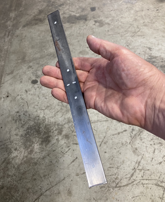
We use 1-1/4" x 1/8" steel strip and cut it on the Ironworker. Mark the overall length of the bar and the line where it should be bent with a highly visible marker. Put dots where the mounting holes will go.
Turn on the power to the Ironworker so the blade rises to the top of its travel.
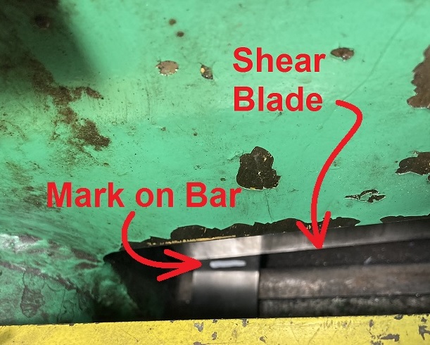
Insert the bar and line up the cut line with the blade of the Ironworker shear.
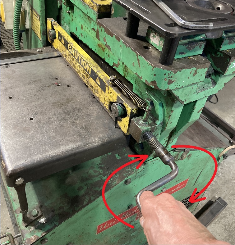
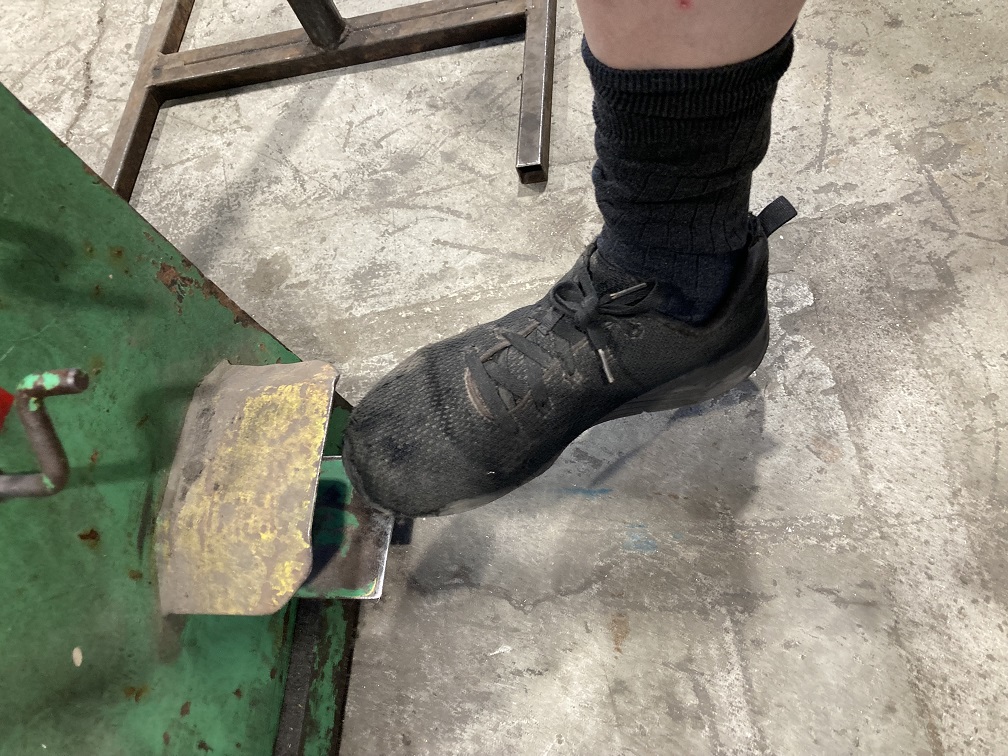
Tigthen down the stock clamp. Depress the foot pedal on the Ironworker to bring the shear blade down.
Release the foot pedal as soon as the bar is cut! DO NOT allow the Ironworker to bottom out!
Punch the Mounting Holes
Now we punch the mounting holes in the blank.
Turn off the power to the Ironworker.
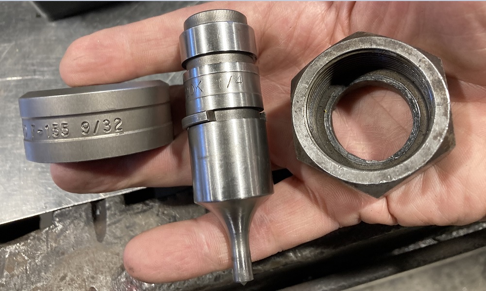
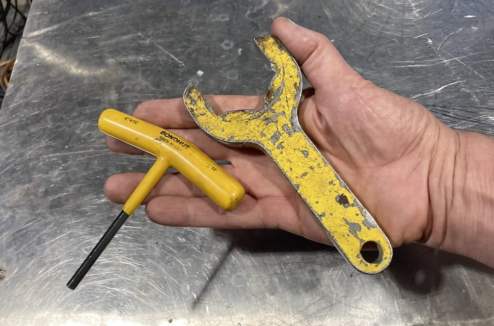
Select the punch and die set for 1/4" holes. Note that the die for 1/4" holes is 1/32" larger in diameter: 9/32". Tools for tightening the punch and die are provided in the tool box.
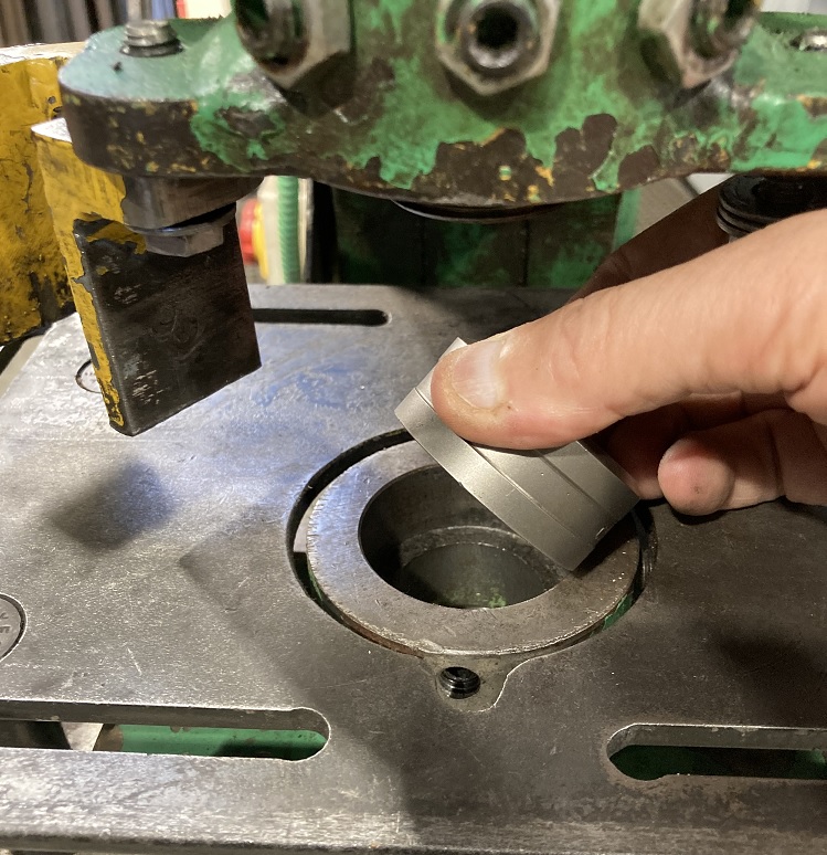
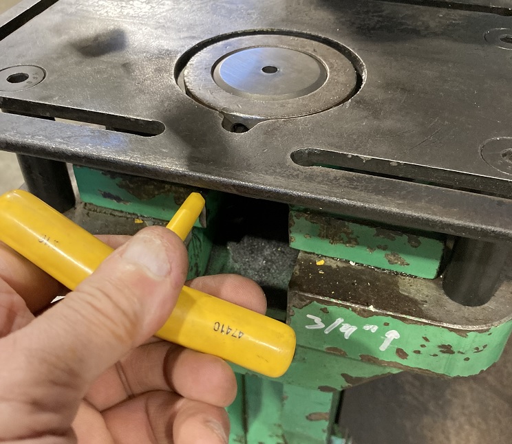
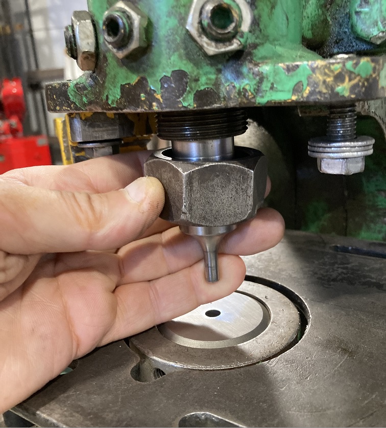
Place the die in the die seat on the punch table with the small hole facing up. Tighten with the hex wrench provided.
Insert the punch into the punch socket and tighten the nut only finger tight prior to aligning it.
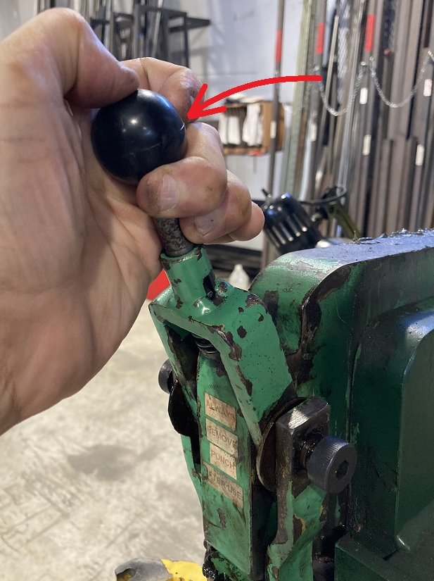
Grab the handle at the top of the punch spindle and pull it down to lower the punch into the die.
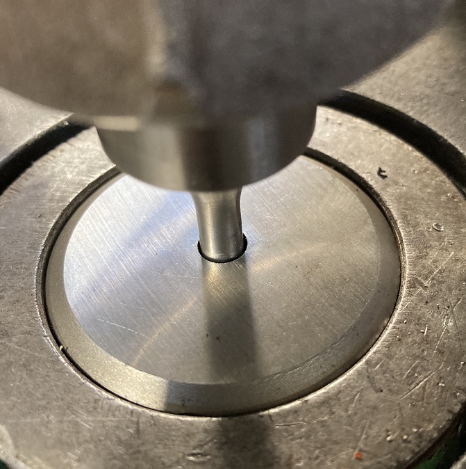
Make sure the punch is centered in the hole in the die. Push it around by hand until it is centered
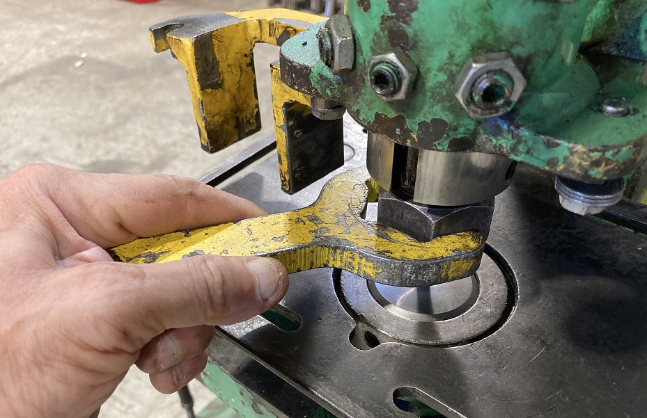
Tighten the punch with the wrench provided and then return the handle to its top position.
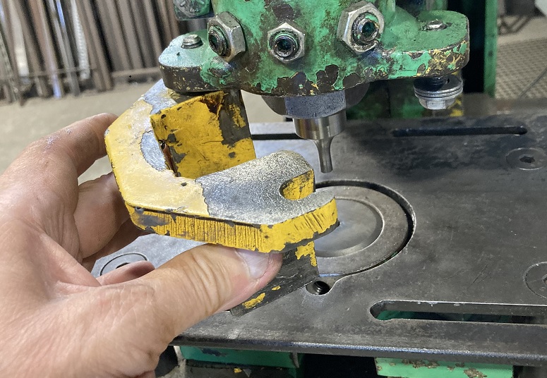
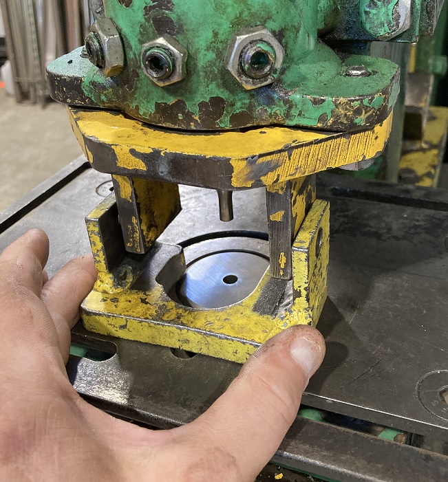
Swing the upper part of the stripper into position.
Place the lower part of the stripper underneath it.
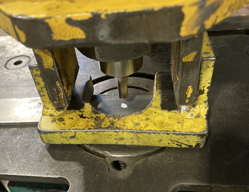
Place the workpiece under the stripper and lower the punch to line it up with the mark. Return the release handle to the top position.
Depress the foot pedal to bring the punch down.
Release the foot pedal as soon as the hole is punched! DO NOT allow the Ironworker to bottom out!
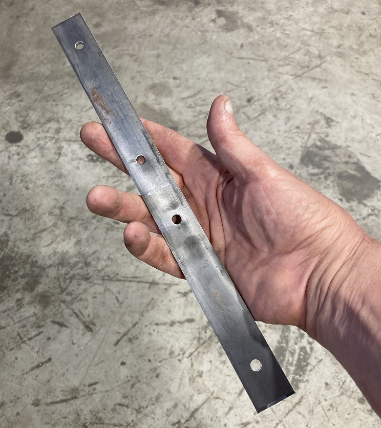
Repeat the process until all of the holes are punched.
Bend the Bracket
This operation uses the Hydraulic Shop Press that can be found in the back of the shop near the chop saws.
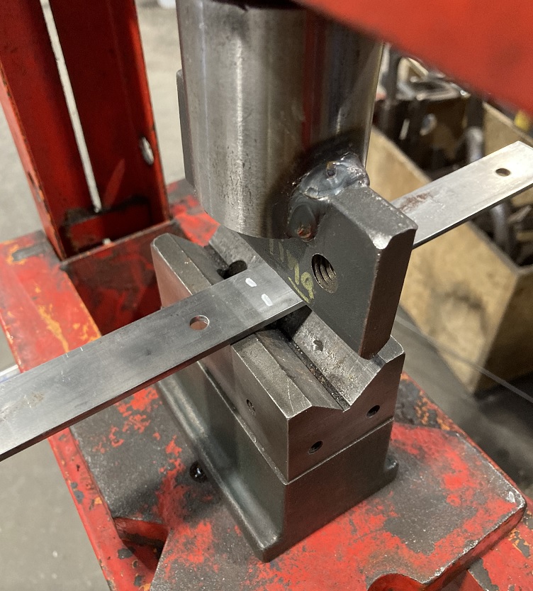
Place the workpiece in the bending tool and lower the tool until it lightly presses against the workpiece.
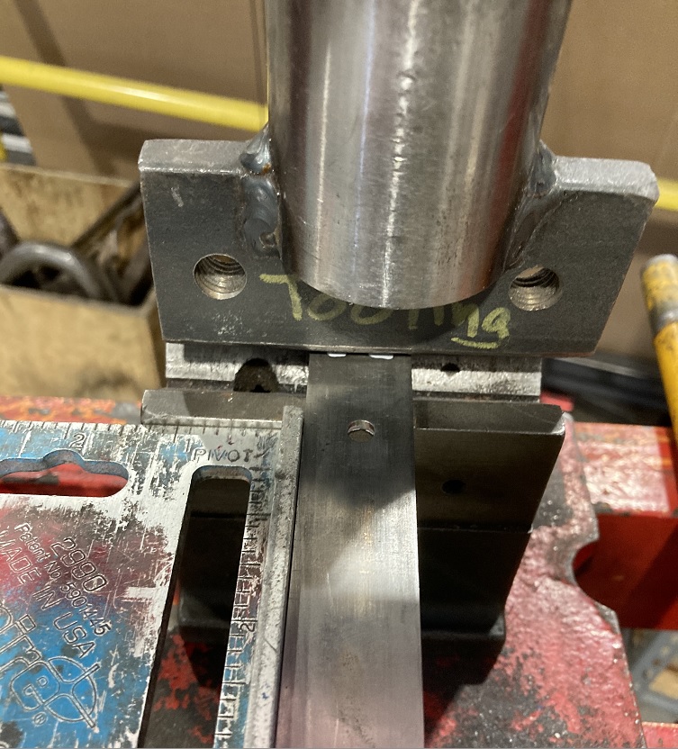
Square up the workpiece in the tool and make sure the bend mark is under the tool.
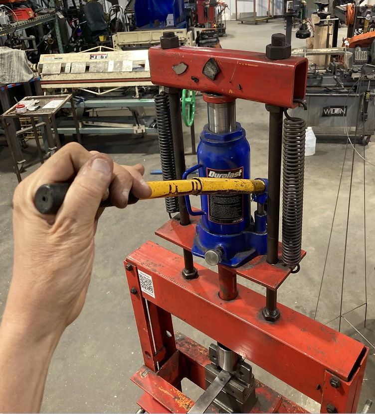
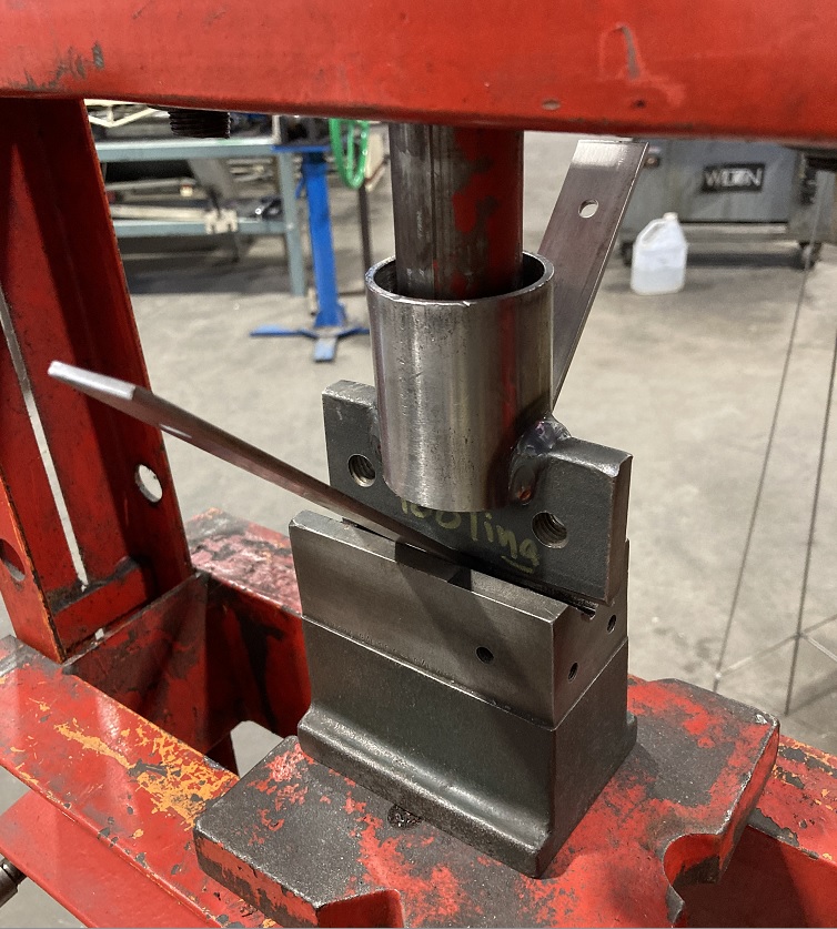
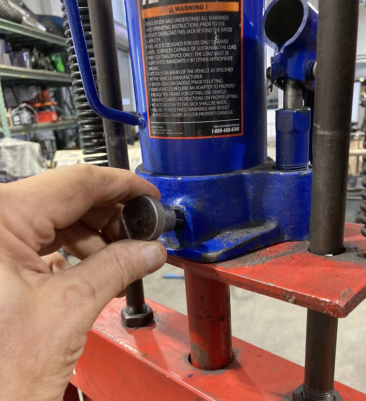
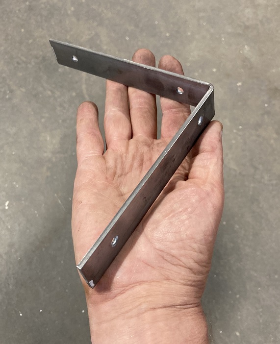
Pump the press and bend the workpiece. Check the angle periodically to make sure it comes out with a right angle.
Cut and Weld the Diagonal Brace
To strengthen the bracket, we add a diagonal brace to the bracket. First we cut it on the Ironworker.
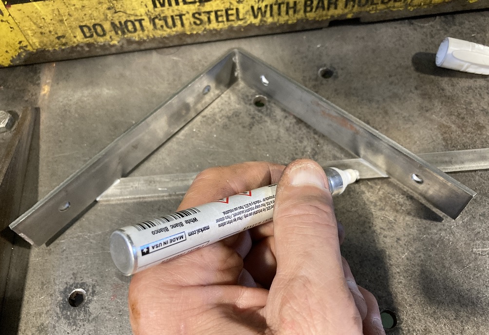
You can measure it, or you can place the bent piece on a piece of bar stock (in this case, 1/2" x 1/8") and mark it. Try to account for the width of the pen tip.
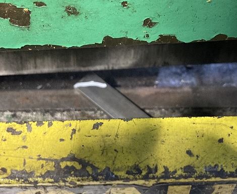
You can insert bar stock at an angle into the Ironworker. Clamp as normal and chop.
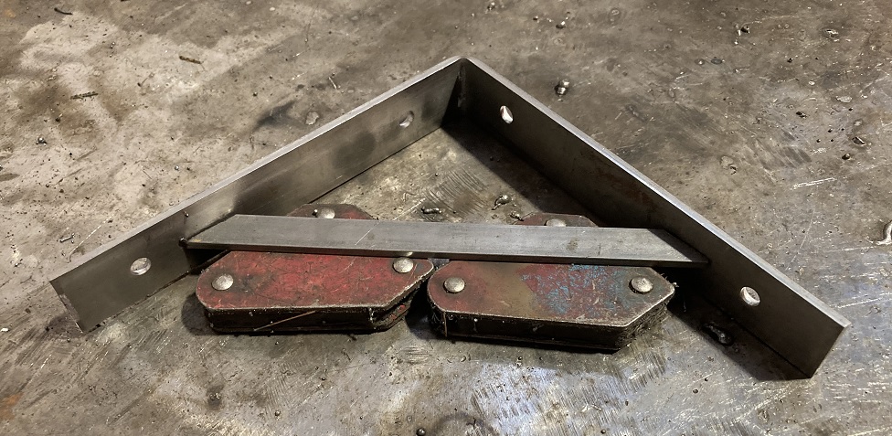
Assemble the angle brace to the bracket on the welding bench. As shown it is held up with welding magnets.
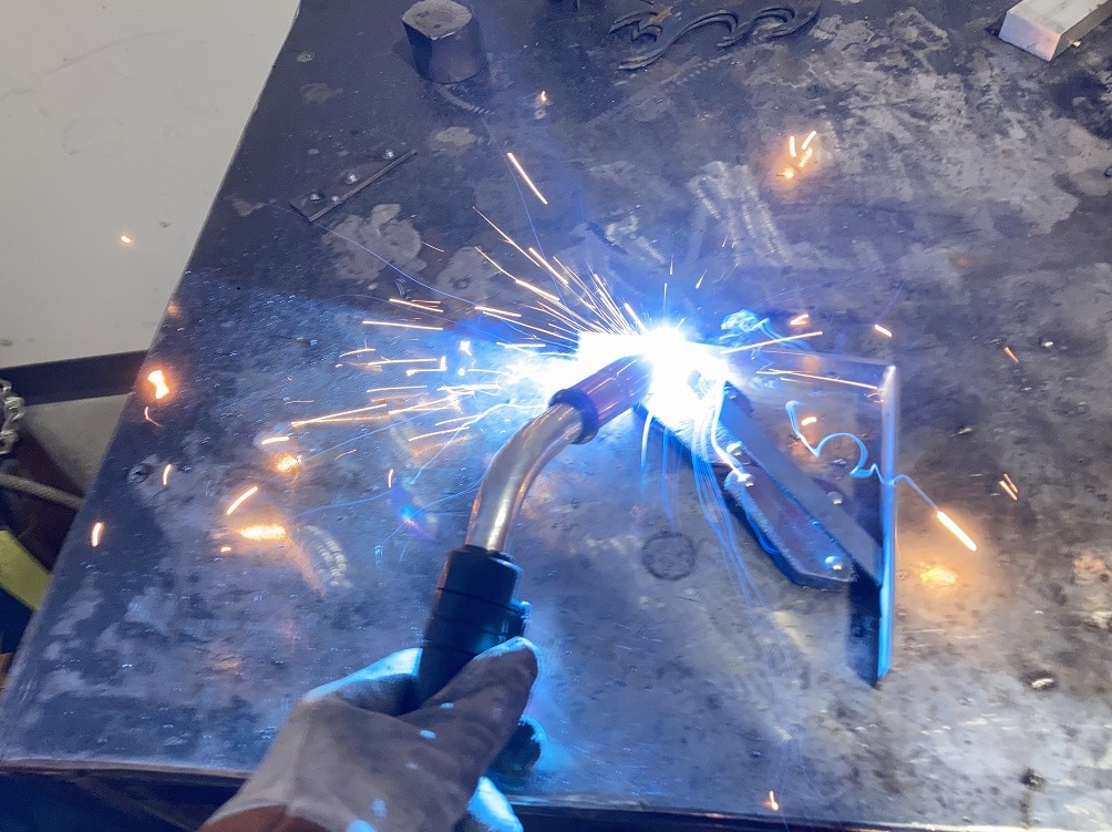
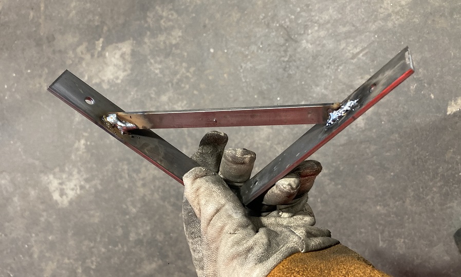
Weld the brace to the bracket with a MIG welder.
The MIG welder is a RED tool. You must be trained and tool-tested in order to use this tool.
Cleaning
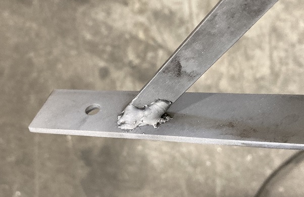
Before finishing the bracket, we will use the sand blaster to clean off oxide and slag residue from the welding process.
This is a RED tool. You must be trained and tool-tested in order to use this tool.
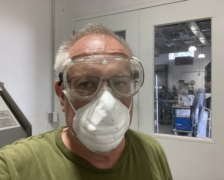
Before working in either the sand-blaster room or the powder-coating room, you MUST don goggles and a dust mask.
Plug in the two-stage dust collector located in the back of the sand-blaster room.
Also switch on the room ventilation fan located adjacent to the CNC plasma cutter.
IF the hopper is empty, add media to the cabinet. Don't add too much. There should only be about 2 quarts of media in the hopper.
Place the workpiece into the sand-blaster cabinet and seal the door shut.
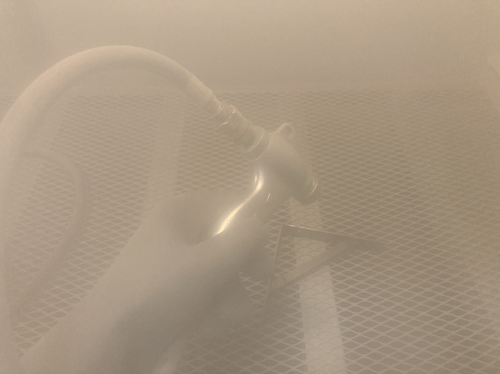
To blast, point the gun at the workpiece and depress the foot pedal.
CAUTION: Wait about two minutes before opening the hatch to the blast cabinet.
The cleaned part should have a granular texture and be uniformly gray in color.
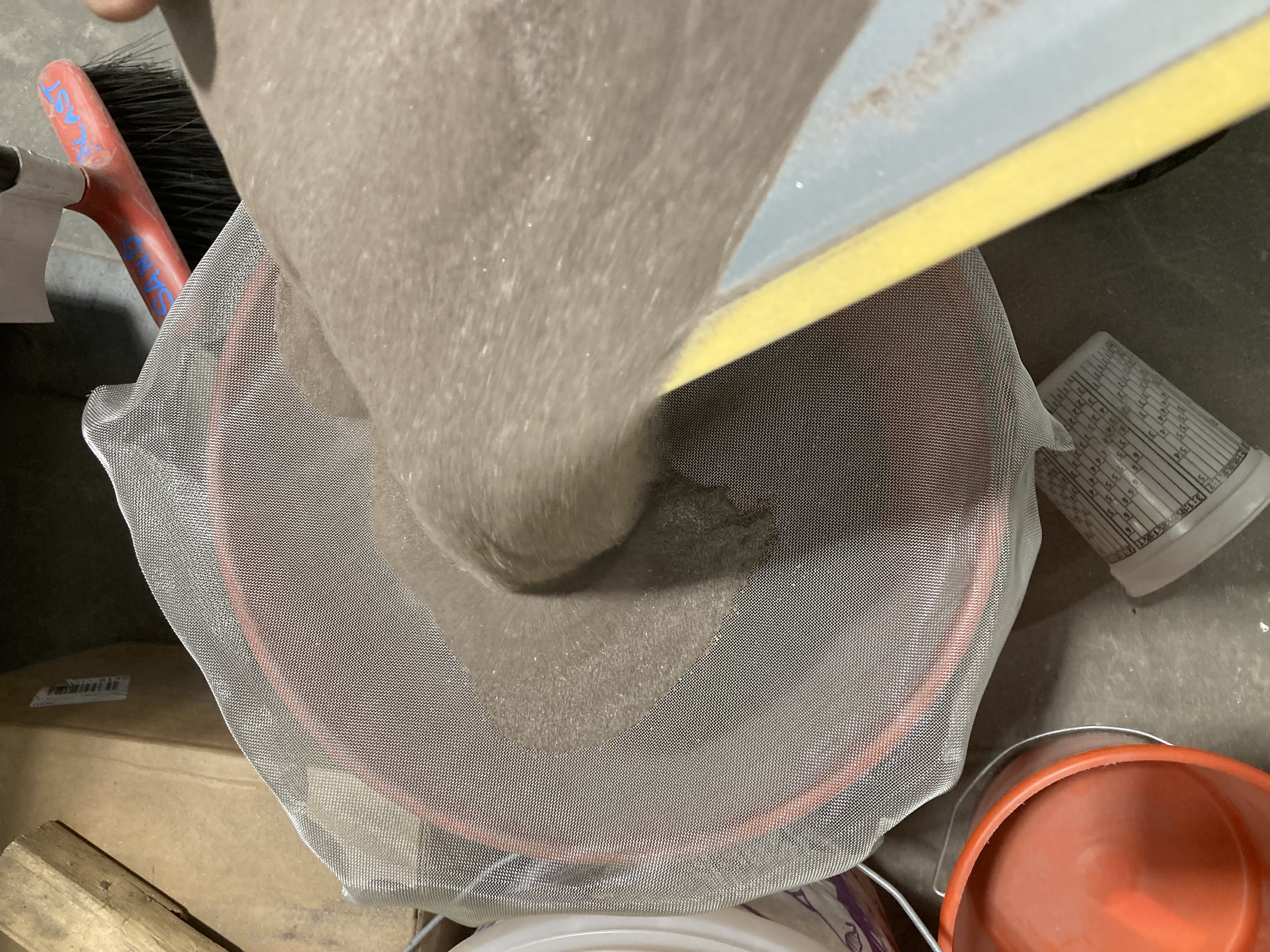
After using the sand blaster, please drain out the media and sift it.
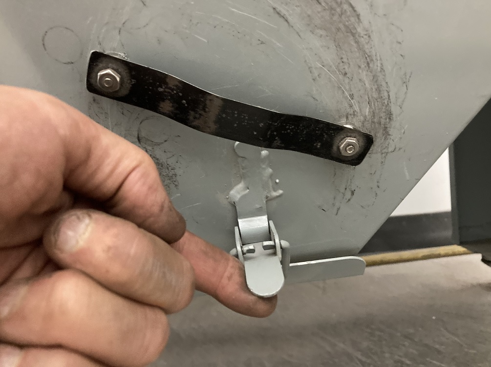
The drain is located at the bottom of the hopper. Place a dustpan or a tray under the drain hatch and open it.
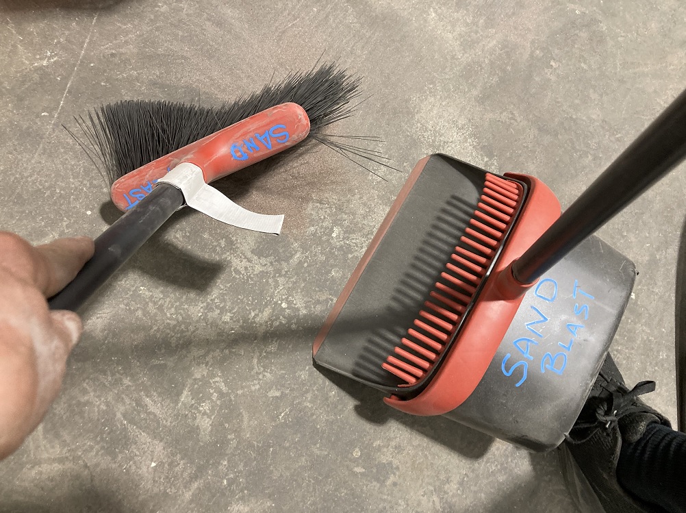
Pour the media through the screen into the storage bucket. Clean up any media that has spilled on the floor.
When leaving, unplug the two-stage dust collector and switch off the lights.
Powder Coating
The bracket is to be finished in the powder coating facility located along the southern wall of the Metal Shop.

