South Bend Manual Lathe: Difference between revisions
No edit summary |
m (display title) |
||
| (19 intermediate revisions by 4 users not shown) | |||
| Line 1: | Line 1: | ||
{{DISPLAYTITLE:South Bend 9A Manual Lathe}} | |||
[[Category:Tools]][[Category:Lathes -- Metal]] | [[Category:Tools]][[Category:Lathes -- Metal]] | ||
Link to:[[:Category:Machine Shop | Machine Shop Main Page]] | Link to:[[:Category:Machine Shop | Machine Shop Main Page]] | ||
{{Warning|text=You must be tool tested to use the South Bend lathe. These instructions are for reference and are not a replacement for training, instruction, or tool testing.}}{{EyeWarning}} | |||
{{EyeWarning}} | |||
{{ToolBox | {{ToolBox | ||
| Line 10: | Line 10: | ||
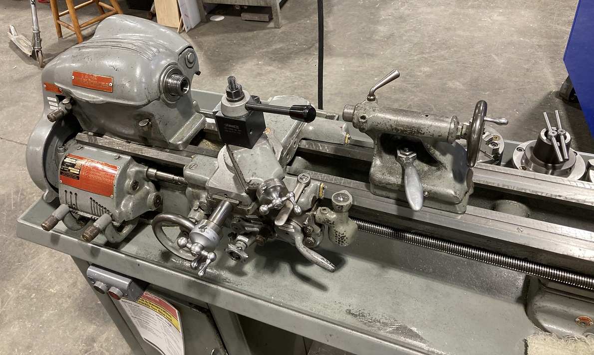
|caption = The South Bend manual bench lathe | |caption = The South Bend manual bench lathe | ||
|make = South Bend | |make = South Bend | ||
|model = | |model = 9A | ||
|serial = | |serial = 53804 NKR 9 | ||
|manufacturer_specs = | |manufacturer_specs = | ||
|manual = [https://drive.google.com/file/d/1seuiCHsli8SDRUk0GXnYwTaPPqchwlbK/view?usp=drive_link Textbook] | |manual = [https://drive.google.com/file/d/1seuiCHsli8SDRUk0GXnYwTaPPqchwlbK/view?usp=drive_link Textbook] | ||
| Line 19: | Line 19: | ||
|testing = [https://www.artisansasylum.com/tool-testing Tool testing] | |testing = [https://www.artisansasylum.com/tool-testing Tool testing] | ||
|restrictions = red | |restrictions = red | ||
|tool_categories = [[:Category:Lathes -- Metal | | |tool_categories = See the [[:Category:Lathes -- Metal | "Lathes - Metal" category page]] for notes on using metal-cutting lathes | ||
}} | }} | ||
==Safety== | ==Safety== | ||
== | Link to: [https://wiki.artisansasylum.com/wiki/Category:Lathes_--_Metal#Safety Safety notes on the Metal-cutting lathes category page] | ||
==Changing the spindle speed== | |||
{| class="infobox" cellspacing="5" style="width: 12em; text-align: left; font-size: 100%; line-height: 1.5em;" | {| class="infobox" cellspacing="5" style="width: 12em; text-align: left; font-size: 100%; line-height: 1.5em;" | ||
! colspan="2" class="infobox-image" | [[File: | ! colspan="2" class="infobox-image" | [[File:Lathe_South_Bend_gearbox_nolabels.png|300px| gearbox]] | ||
|- | |- | ||
| colspan="2" | The | | colspan="2" | The South Bend lathe gear-box | ||
|- | |- | ||
|} | |} | ||
This lathe features manual speed-changing where the user actually manipulates belts and gears inside the gearbox itself. | |||
Do not attempt to adjust these items unless you have been properly trained and tool-tested. | |||
=== Belts and Pulleys === | |||
The South Bend has two belts. The V-belt between the motor and the lathe drive shifts between high range and low range, and the flat belt between the lathe drive and the spindle allows adjustments within these ranges. To adjust the speed, loosen the belt tension lever on the left side of the machine, then move the belts to achieve the appropriate speed. Tighten the belt tension when you're ready to use the lathe | |||
[[File:Sb motor and belts annotated.jpeg|alt=South Bend motor and drive belts|thumb|Motor, motor belt, and drive belt under the South Bend lathe. The motor belt (a) switches between the high speed range and the low speed range, and the orange leather drive belt (b) allows three different speeds within each range. Note that the loose belt tension here; adjusting either belt requires loosening the belt tension.]] | |||
[picture of belt tension lever] [picture/chart of lathe speeds] | |||
=== Back Gear === | |||
The back gear control on the lathe allows low speed, high torque rotation. To use the back gear, pull the back gear lever until the back gears engage with the spindle gear. If the gears are not meshing, manually spin the chuck while pulling the back gear lever to the rear. | |||
Next, pull the coupling pin out of the largest drive gear. If you don't remove this pin, the chuck and gears will be locked. This will prevent the spindle from turning, and it's useful for loosening the chucks, but operating the lathe in this condition will cause the belts to rub. | |||
The additional mechanical components in the back gear drivetrain creates more mechanical, gear-clanging noise. This noise is normal, but grinding or rubbing noises are not. Stop the lathe if you hear these kinds of noises. | |||
To disable the back gear, move the back gear lever to the rear to disengage the back gear and re-insert the coupling pin. Ensure that the pin is fully seated in the cutout, which is in-line with the oil port on the middle spindle pulley. | |||
== Power Feed == | |||
[[File:Sb back gear and locking pin.jpeg|alt=Overview of the South Bend headstock spindle controls|thumb|Overview of the headstock spindle controls on the South Bend lathe. To engage back gear, pull the back gear lever (a) towards the front of the lathe and pull out the coupling pin (b). To disengage back gear, push the back gear lever towards the rear of the lathe and push in the coupling pin. Align the coupling pin with the oil port (c) before trying to push the coupling pin back into place.]] | |||
The South Bend has both power carriage feed and power cross feed. The keyway in the leadscrew powers this power feeding, so the leadscrew must be enabled to use power feed. With the lathe powered off, enable the power feed by moving the power feed lever out of the neutral position and into the appropriate direction. Note that turning and facing operations typically require different power feed lever settings.[[File:Sb power feed settings.jpeg|alt=Overview of South Bend headstock power feed and thread pitch controls|thumb|Overview of South Bend headstock power feed and thread pitch controls. To engage power feed, move the power feed lever (a) out of the center neutral position and into the position for the desired feed direction. Use the power feed/thread pitch adjustment levers (b) to adjust the feed rate (or thread pitch, if you're cutting threads)]]With the lathe still powered off, move the power feed lever on the apron to the appropriate setting. Loosen the clutch knob to disengage the power feed before turning on the lathe. Tighten the clutch knob to engage the power feed, and confirm that the correct control knob is turning in the correct direction. Disengage the power feed by loosening the clutch.[[File:Sb apron controls.jpeg|alt=Overview of South Bend apron controls|thumb|Overview of South Bend apron controls. To enable power carriage feed, move the power feed selector (a) out of the central neutral position to the top position. Move it to the bottom position for power cross feed. To activate power feed, tighten the clutch knob (b). The half nut (c) and thread dial (d) are in this picture too, but they're for cutting single point threads, not power feed.]]Two levers control the speed of the power feed. The leftmost position of these levers is the fastest feed speed, while the rightmost position is the slowest. Position E has a good range of feed rates, and this is typically the right setting for the first lever. | |||
== Installing and Removing Chucks == | |||
The South Bend 9A has a threaded spindle. Remove the chuck by locking the spindle into back gear and using an adjustable wrench and mallet to loosen the chuck from the spindle | |||
[[File:Sb removing chuck.jpeg|alt=Removing a chuck from the South Bend lathe|thumb|Removing a chuck from the South Bend lathe. Lock the spindle with the back gear lever and coupling pin to prevent the spindle from rotating while you unthread the chuck. Use an adjustable wrench to grab one of the chuck jaws, then hit the wrench with a mallet to loosen the threads holding the chuck to the spindle.]] | |||
Install a new chuck by reversing this process; screw the back of the chuck onto the threads of the spindle. The rotation of the spindle will tighten the threads of the chuck to the threads of the spindle, so you don't need the mallet to lock the chuck to the spindle. | |||
Latest revision as of 10:55, 13 June 2025
Link to: Machine Shop Main Page
| You must be tool tested to use the South Bend lathe. These instructions are for reference and are not a replacement for training, instruction, or tool testing. | |
|---|---|
| Eye protection required! | ||
|---|---|---|
| South Bend Lathe | |
|---|---|
| General Info | |
| Make | South Bend |
| Model | 9A |
| Serial | 53804 NKR 9 |
| Specs | |
| Manual | Textbook |
| Asylum Info | |
| Location | Machine Shop |
| Rubric | N/A |
| Training | |
| Testing | Tool testing |
| Restrictions | red |
See the "Lathes - Metal" category page for notes on using metal-cutting lathes
Safety
Link to: Safety notes on the Metal-cutting lathes category page
Changing the spindle speed
| |
|---|---|
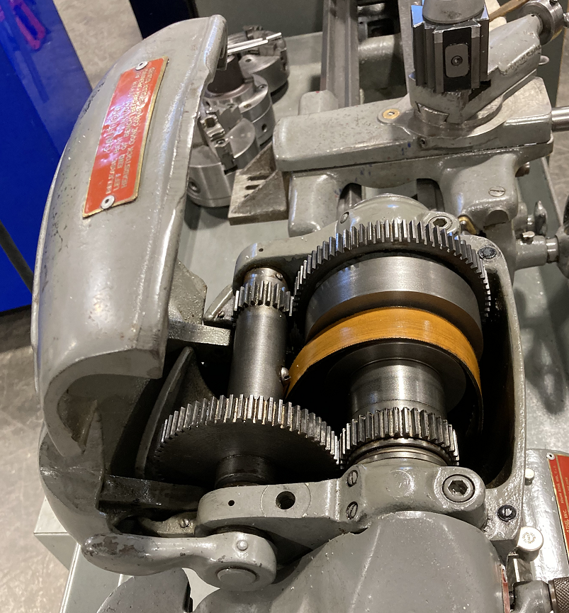
| The South Bend lathe gear-box |
This lathe features manual speed-changing where the user actually manipulates belts and gears inside the gearbox itself.
Do not attempt to adjust these items unless you have been properly trained and tool-tested.
Belts and Pulleys
The South Bend has two belts. The V-belt between the motor and the lathe drive shifts between high range and low range, and the flat belt between the lathe drive and the spindle allows adjustments within these ranges. To adjust the speed, loosen the belt tension lever on the left side of the machine, then move the belts to achieve the appropriate speed. Tighten the belt tension when you're ready to use the lathe
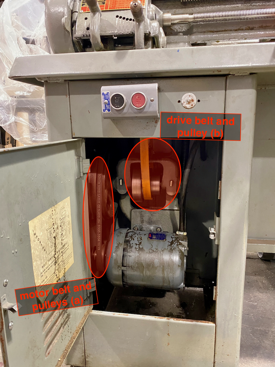
[picture of belt tension lever] [picture/chart of lathe speeds]
Back Gear
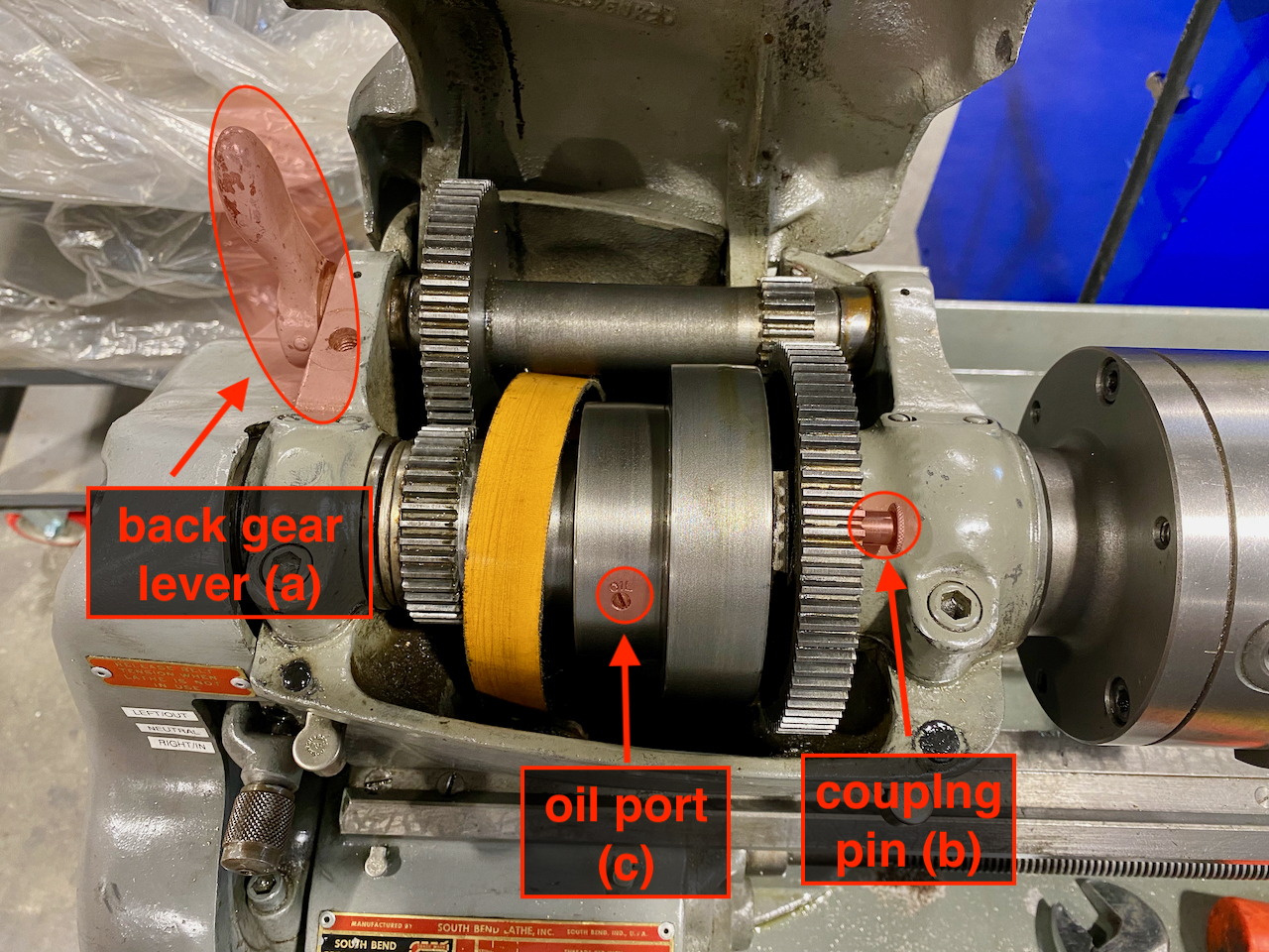
The back gear control on the lathe allows low speed, high torque rotation. To use the back gear, pull the back gear lever until the back gears engage with the spindle gear. If the gears are not meshing, manually spin the chuck while pulling the back gear lever to the rear.
Next, pull the coupling pin out of the largest drive gear. If you don't remove this pin, the chuck and gears will be locked. This will prevent the spindle from turning, and it's useful for loosening the chucks, but operating the lathe in this condition will cause the belts to rub.
The additional mechanical components in the back gear drivetrain creates more mechanical, gear-clanging noise. This noise is normal, but grinding or rubbing noises are not. Stop the lathe if you hear these kinds of noises.
To disable the back gear, move the back gear lever to the rear to disengage the back gear and re-insert the coupling pin. Ensure that the pin is fully seated in the cutout, which is in-line with the oil port on the middle spindle pulley.
Power Feed
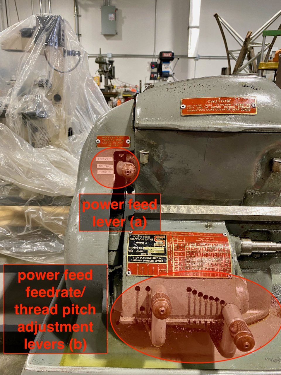
The South Bend has both power carriage feed and power cross feed. The keyway in the leadscrew powers this power feeding, so the leadscrew must be enabled to use power feed. With the lathe powered off, enable the power feed by moving the power feed lever out of the neutral position and into the appropriate direction. Note that turning and facing operations typically require different power feed lever settings.
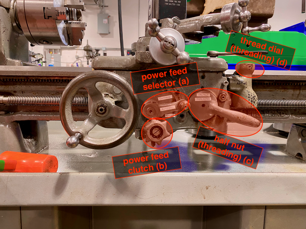
With the lathe still powered off, move the power feed lever on the apron to the appropriate setting. Loosen the clutch knob to disengage the power feed before turning on the lathe. Tighten the clutch knob to engage the power feed, and confirm that the correct control knob is turning in the correct direction. Disengage the power feed by loosening the clutch.
Two levers control the speed of the power feed. The leftmost position of these levers is the fastest feed speed, while the rightmost position is the slowest. Position E has a good range of feed rates, and this is typically the right setting for the first lever.
Installing and Removing Chucks
The South Bend 9A has a threaded spindle. Remove the chuck by locking the spindle into back gear and using an adjustable wrench and mallet to loosen the chuck from the spindle
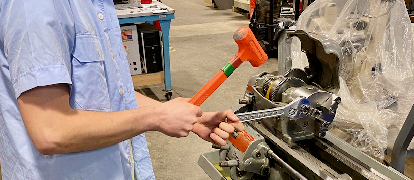
Install a new chuck by reversing this process; screw the back of the chuck onto the threads of the spindle. The rotation of the spindle will tighten the threads of the chuck to the threads of the spindle, so you don't need the mallet to lock the chuck to the spindle.
