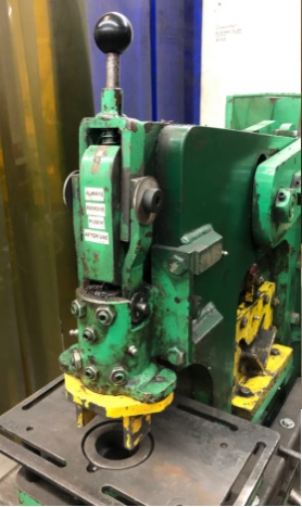
Ironworker
| Ironworker | |
|---|---|
| General Info | |
| Make | Uni-Hydro |
| Model | 42-14 |
| Serial | Unknown |
| Specs | n/a |
| Manual | N/A |
| Asylum Info | |
| Location | Metal Shop |
| Rubric | n/a |
| Training | Tool classes |
| Testing | Tool testing, or come to the shop on Tool Testing Night |
| Restrictions | red |
Materials
Use for:
- Mild Steel Only: plate, bar, angle
Do not use for:
- Hardened Steel
- Stainless
- Aluminum and other soft metals
Safety Hazards
- Workpiece can unexpectedly snap.
- Eye protection required.
- Don’t pinch your fingers between the machine and the workpiece as the shears perform the cut.
- Cuts/ scrapes from sharp cut edges of work
- Pieces falling on your feet after the cut.
| Eye protection required! | ||
|---|---|---|
Operation Notes
| |
|---|---|
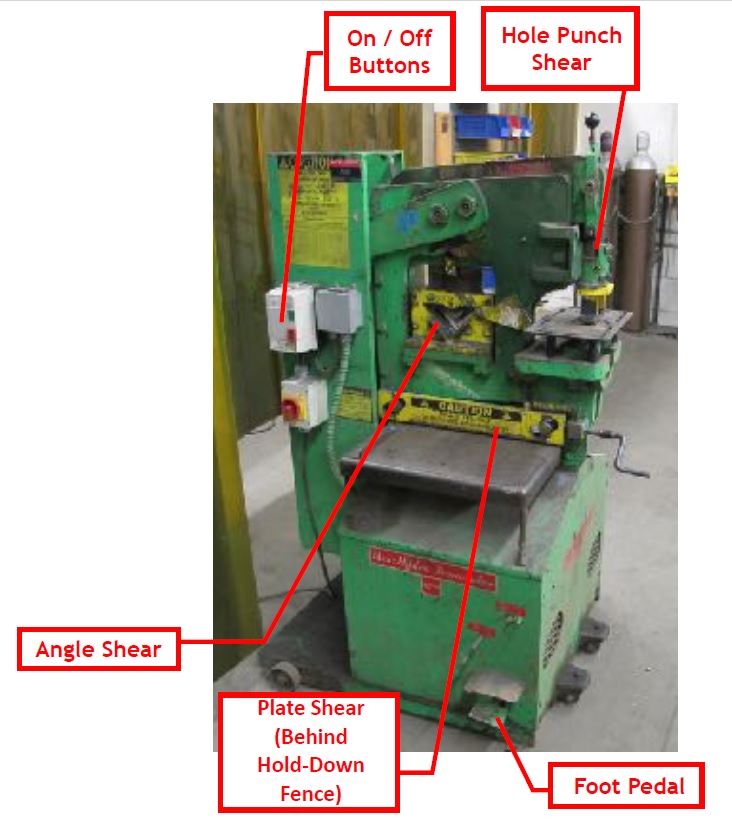
| Ironworker |
- Machine has three sets of shears: for plate, for angle, and for removable dies to punch holes. Never use more than one shear at a time.
- Remove all hole punches and dies from machine when punching operation is complete. (Reduces wear and tear, breakage.)
- Use hold-down clamps to secure work. (Also keeps workpiece level during cut.)
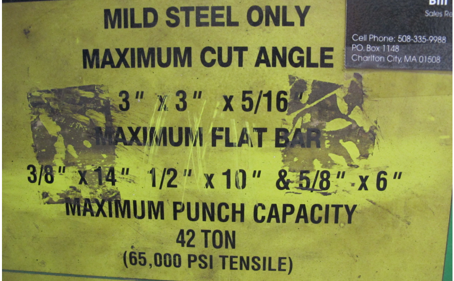
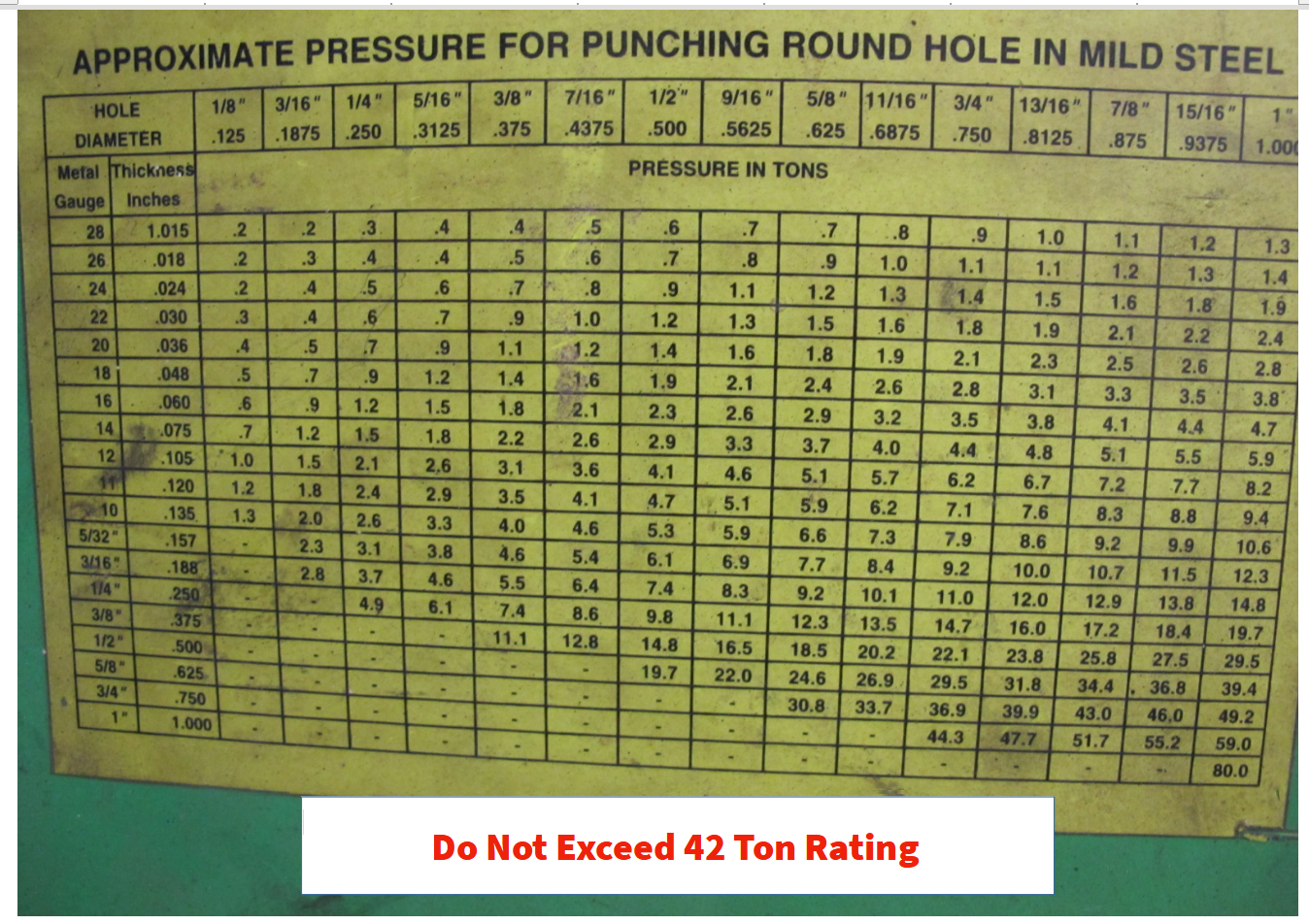
- Maximum workpiece size is listed on the machine (yellow labels). Do not exceed the 42 ton rating. Minimum work size is not clear.
- When punching holes, the hole must be larger in diameter than the thickness of the material – you can’t punch a ¼” hole in ¼” bar
- Learn to use foot pedal to line up your cuts. (For steel plate and angle, lower shear position using the foot pedal.)
- When changing punch operation, always recheck die for misalignment.
- Small amounts of oil on the steel smooths punching operation, especially on harder steels.
- For production punching, apply oil to the punch and die after every 8 to 10 holes punched.
Basic Operating Instructions
| Never perform more than one cut / punch at a time! | |
|---|---|
| |
|---|---|
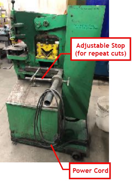
| Back of Ironworker |
1. Perform a safety check prior to use
- Clear all cutting areas. Remove debris from prior cuts at backside of machine. If not using hole punch dies, remove them.
- Check to make sure your workpiece does not exceed machine’s capacity.
- For extra safety, turn machine on only when operating the foot petal. Turn machine off when performing other adjustments.
2. Plug machine into a welding bay outlet.
3. Insert and secure the workpiece.
- Press the green button to turn the machine on. The cutting blades will automatically move to their highest point.
- Optional: Using the foot petal, adjust shear to a height appropriate for your alignment needs. (Especially useful when using the plate shear.)
- Turn the machine off.
- Insert workpiece and align with cutting blades.
- Optional: Mark your pieces as needed to help with alignment. (Sharpie works well.)
- Secure workpiece. For plate, use the crank to tighten the Hold-Down Fence. For angle, flip the safety fence into place. For hole punching, keep the machine at its highest position, insert the stripper assembly correctly, and align the punch with the die. (See instructions on punch installation.)
- Optional: Use Adjustable Stop on back of machine for repeat cuts.
4. Press the green “On” button to turn the machine on, then step on foot petal to perform the cut / punch.
5. Turn machine off. Remove workpiece and clear cut debris from the machine.
Punch Installation / Basic Operation
| |
|---|---|
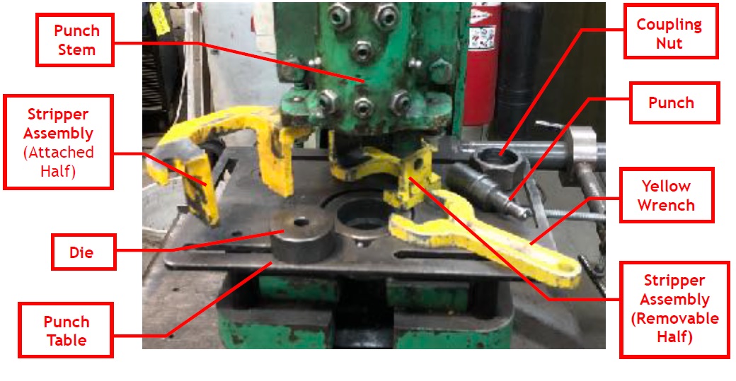
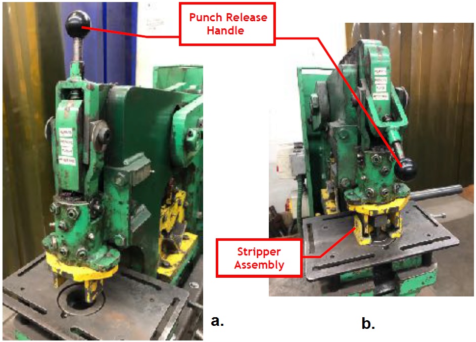
| Parts of the Punch and Die Assembly |
| |
|---|---|
| a. Normal Configuration - Punch not in use. --- b. Punch Installed, with punch release handle lowered to check die alignment. |
1. Check size markings on the punch and die to verify that they match.
Punches can break if mismatched or abused.
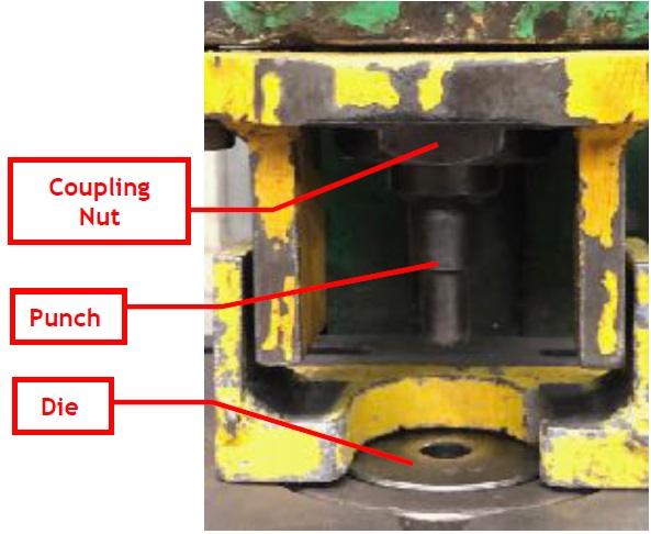
2. Place the Punch into the Coupling Nut and secure to the punch stem using the yellow wrench.
3. Insert the Die into the round hole in Punch Table.
Wider side of hole in die faces down, allowing the slug to fall to the floor during the punch operation.
4. Test for punch alignment by lowering the Punch Release Handle.
Return the Punch Release Handle to the upright (locked) position when done.
The punch should be aligned with the die. If not, use a wrench to loosen the bolts below the punch table, adjust, and retighten.
5. Place workpiece on table.
Use Punch Release Handle for alignment.
| |
|---|---|
| Punch Close-up. |
6. Insert and align the removable half of the stripper assembly.
Double check to make sure the two halves of the Stripper Assembly align properly, both with each other and also with the workpiece.
- When aligned properly, the Stripper assembly will remove the punch from the workpiece on the machine’s upward stroke. The removable half of the stripper assembly locks with the attached half of the assembly to hold the workpiece down as the machine extracts the punch from the hole.
- Make sure to understand the above mechanics. It’s no fun when a punch gets stuck the workpiece.
7. Turn the machine on and use the foot petal to perform the punch.
8. Turn the machine off.
Remove workpiece. When done, remove the punch and, and disassemble the Stripper Assembly.
| |
|---|---|
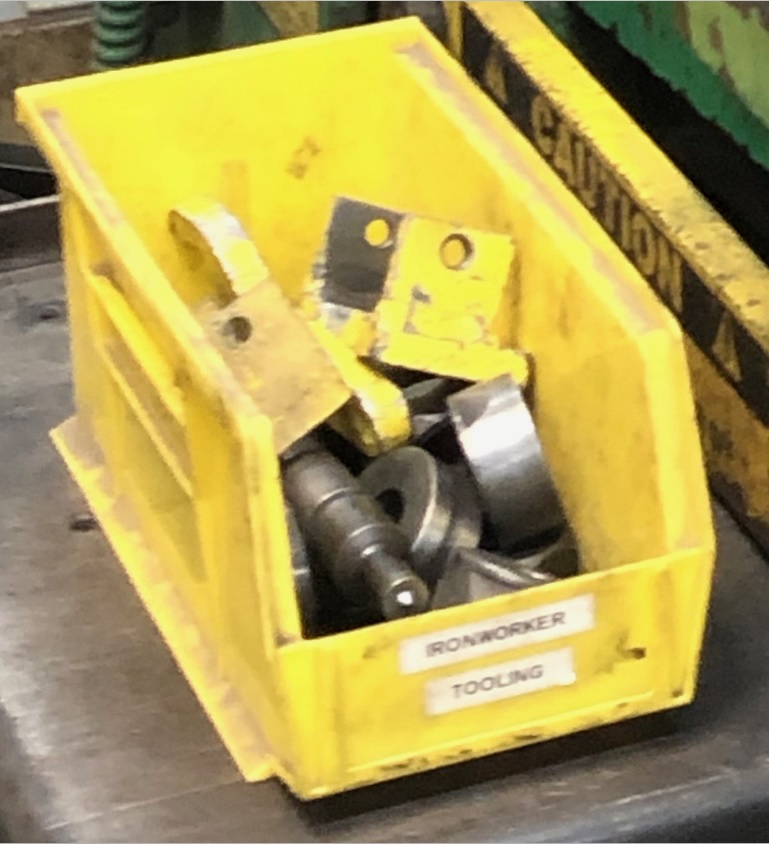
| Punches are kept in a yellow bin adjacent to the machine. |
Supplementary Information
| |
|---|---|
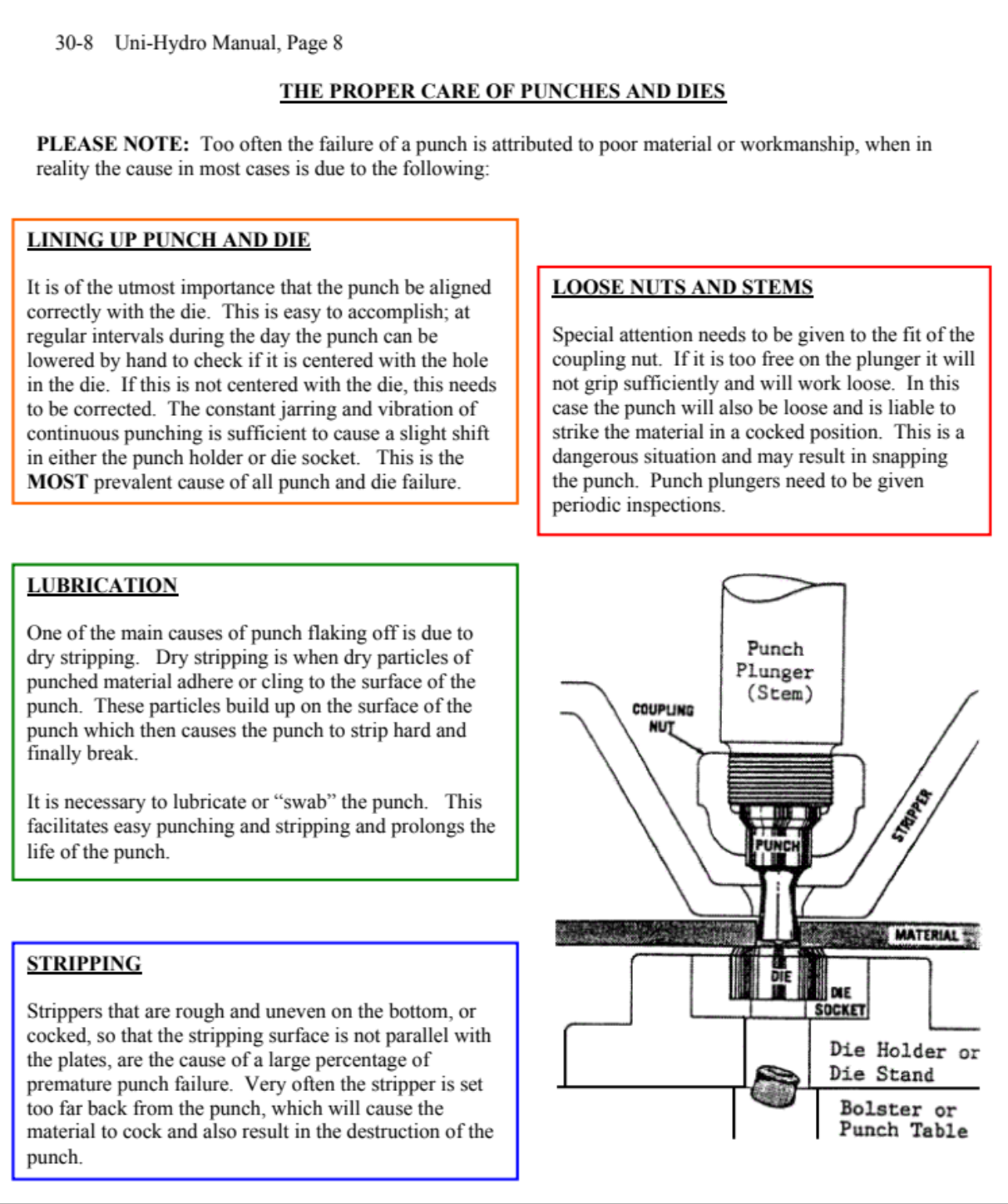
| Excerpt from Ironworker Manual |
| |
|---|---|
| Antique Label on Ironworker Showing the Maximum Stock Sizes |
| |
|---|---|
| Antique Label on Ironworker Showing the Force to Punch Holes in Plates. |
