Brackets Tutorial 2b: Fabricating a Bracket from a Solidworks Design
Link to: Bracketage Main Page
Backward to: Tutorial 2a
Solidworks and Metal Shop tutorial by Jim Bredt 20240611
Introduction
This tutorial is the continuation of an earlier tutorial where an existing metal bracket was rendered in Solidworks.
Here we will show how to export the Solidworks data to the Torchmate CNC plasma cutter located in the Metal Shop at Artisans Asylum. After cutting the flat piece from steel sheet it is bent into shape and welded at the seams.
Load the Solidworks Design
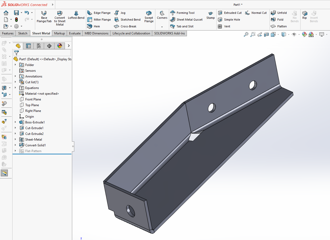
In the previous Solidworks tutorial a design was created for a sheet metal bracket. Load this design into Solidworks now.
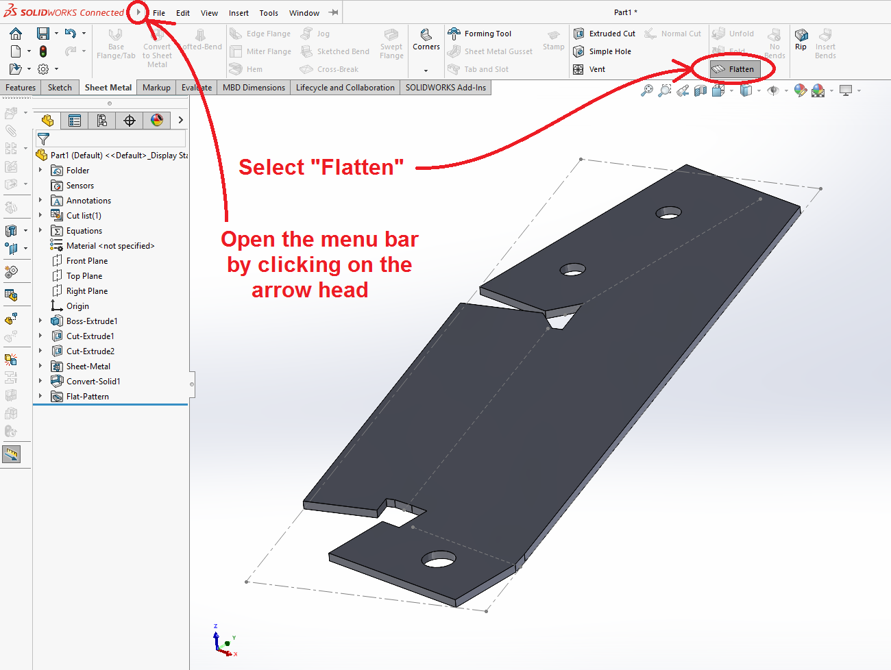
Under the "Sheet Metal" tab, click on the "Flatten" tool to render the design without the bends.
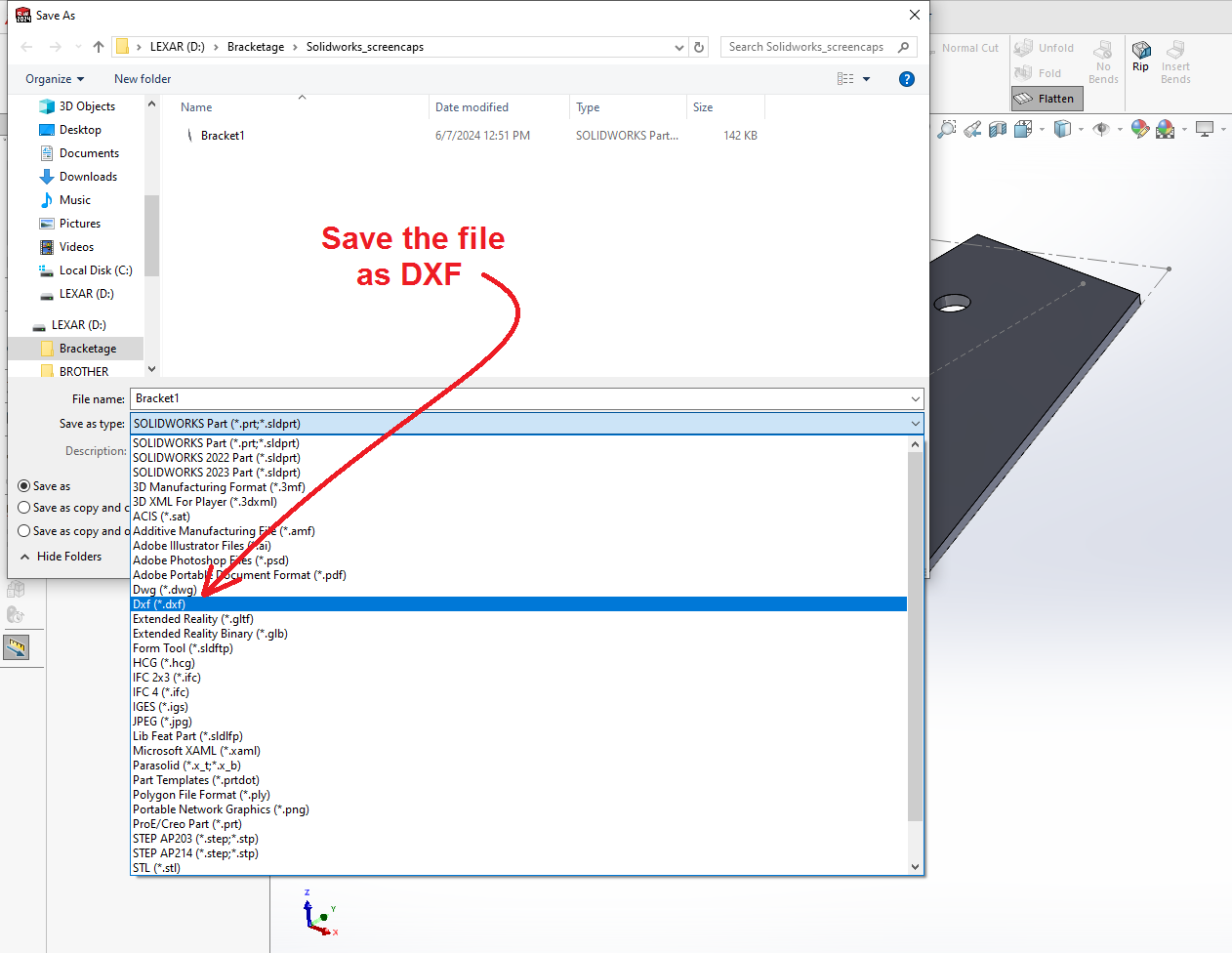
Save the Part in DXF Format
Next we export a DXF file. Click on the (![]() ) small arrowhead next to the Solidworks logo at the top left corner of the window. This will open up a conventional menu bar. Select "File" and then "Save As New". Browse to the desired location (such as your USB thumb drive) and choose a file name.
) small arrowhead next to the Solidworks logo at the top left corner of the window. This will open up a conventional menu bar. Select "File" and then "Save As New". Browse to the desired location (such as your USB thumb drive) and choose a file name.
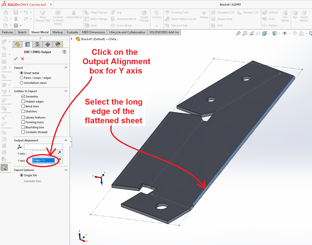
A listing opens in the left margin of the window (below left) that allows you to select an edge in the design and make it parallel to one of the axes on the CNC machine.
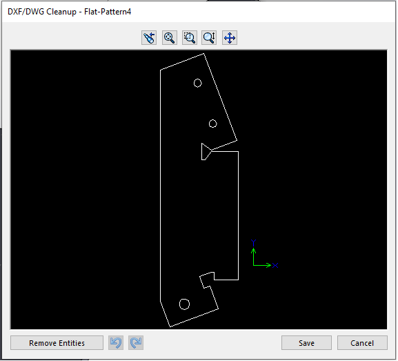
Click on the (![]() ) green check mark and another window opens that shows the contour of the cut in the DXF file. This window allows you to select erroneous features and exclude them from the saved file. Click on "Save".
) green check mark and another window opens that shows the contour of the cut in the DXF file. This window allows you to select erroneous features and exclude them from the saved file. Click on "Save".
Import DXF into Torchmate
Run the Torchmate software. There are copies of the program on all of the Solidworks computers at AA. These can be used to check the validity of the data. To set up to cut the part, you need to move the DXF file via a USB thumb drive to the computer attached to the CNC plasma cutter.
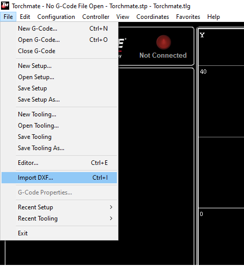
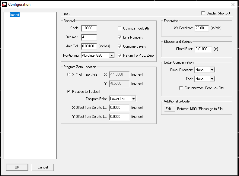
On the "File" menu, select "Import DXF..." This will open a "Save As" dialog box asking for a file name and location of the converted data. Then it will open a second dialog box asking for data on certain parameters. For the most part the machine defaults should be okay. With experience you may find adjustments to make at this stage.
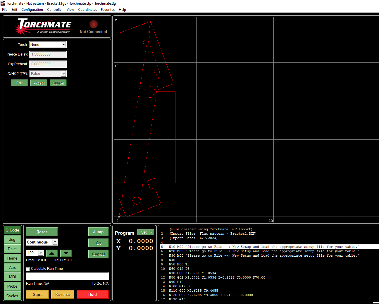
When you click "Okay" the contour of the cut should appear in red in the graphic window on the screen. The "G-Code" representation of the cut appears at the bottom of the screen. Double-clicking on this code listing will open an Edit box that allows the data to be changed manually.
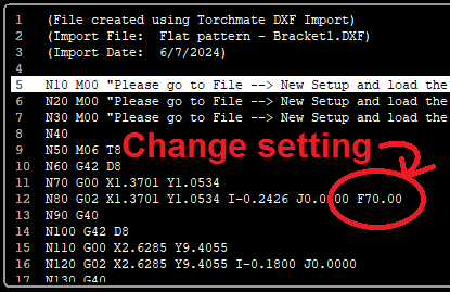
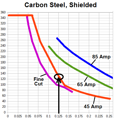
Check the speed setting for the cut. The graph below right indicates the speed should be about 120 inches/min for 1/8" sheet. If the nozzle is worn, you may need to reduce it to 110 or 100. See Line 12 in the photo below left. The statement "F70.00" needs to be changed to "F110" in the Edit window. Double-click on the code listing to open the edit window and change the speed setting.
This setting might have been inserted into the "DXF Import" window, but usually this detail is uncertain when that operation is performed.
You are now ready to cut the sheet. If you are unsure what to do, please review the user training document. This is a red tool. You must be trained and tool-tested to use it.
Set up the Cut
Get a sheet of 1/8" steel that is at least 12½" x 3½" in size. Place it on the cutting bed with the long axis oriented in the Y (transverse) direction of the table.
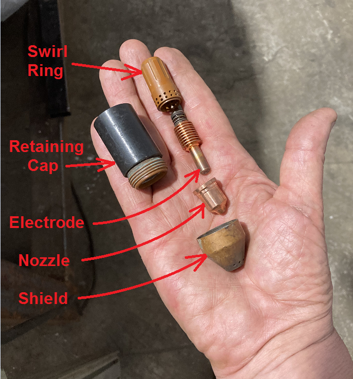
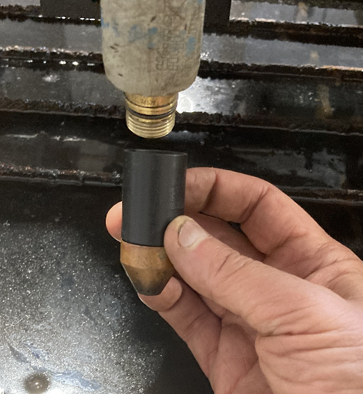
Install a nozzle. For cutting 1/8" steel, use the 45-Amp nozzle hardware.
Jog the torch over to a clean section of metal sheet in the correct orientation.
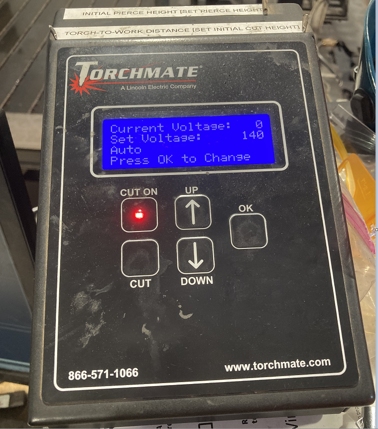
Verify that all of the settings on the torch height control are correct (refer to the user training document) and arm the torch.
Cut the Part
| Eye protection required! | ||
|---|---|---|
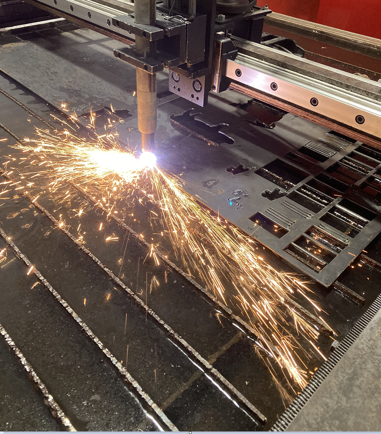
Put on shaded goggles and hit the "Start" button on the computer to start cutting.
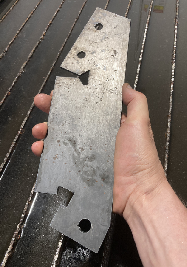
Shown below is the flat piece for the bracket as cut. Compare with the flat design at the top of this document.
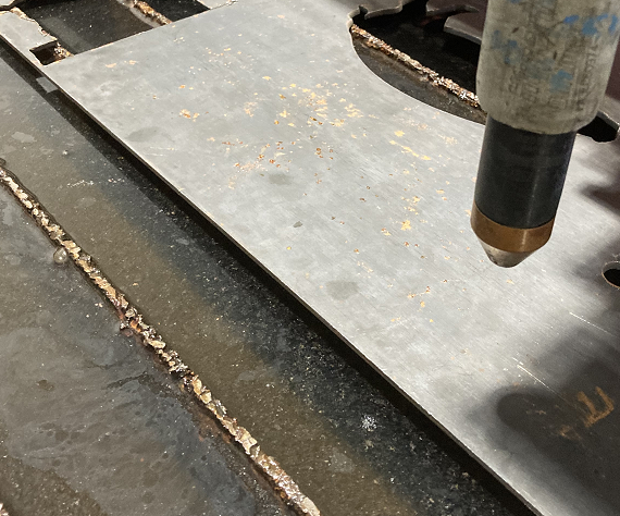
Sometimes you will find some dross adhering to the bottom edge of cuts made on the plasmatron. Often this material flakes off very easily, but occasionally it is necessary to grind the edges of the workpiece.
Bend the Sheet
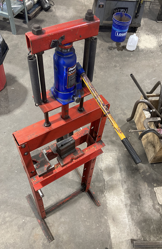
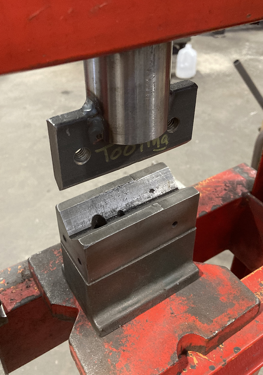
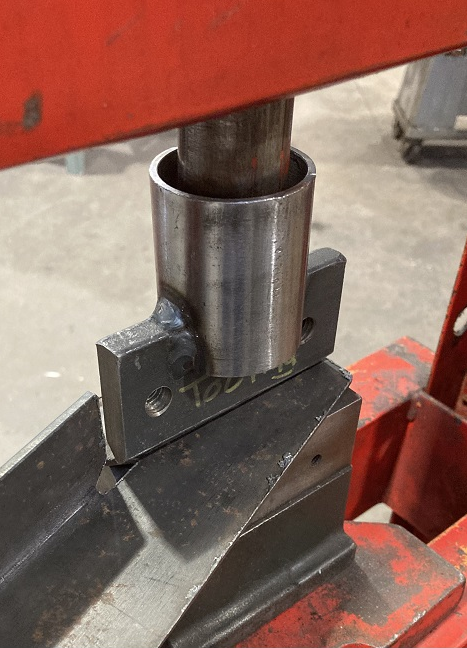
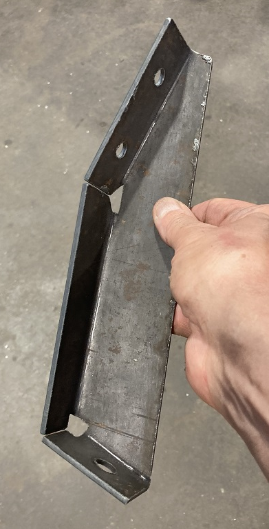
The 1/8" sheet used in this project is too thick to be bent on the shop box and pan brake. To make the bends in the bracket, use the hydraulic press with its bending hardware installed.
Mark lines on the sheet with a Sharpie marker to help line the bends up on the tool. Place all of the components carefully and pump the handle gradually. Check the bend with a square periodically to ensure you don't overshoot and make a bend greater than 90°.
Weld the Bracket
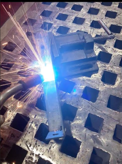
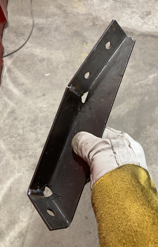
The welds in this design are outside of the main stress path, so the strength of the bracket isn't too sensitive to the quality of the welds. MIG welding is the most convenient method to use on this part. These welders are red tools. Training and tool-testing are required.
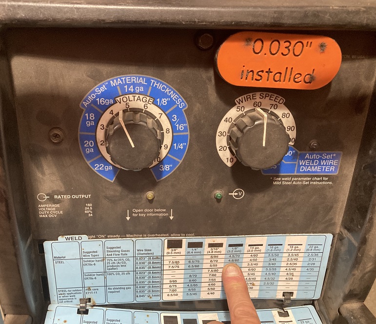
The ideal settings for the machine are found on a pull-down reference on the front panel.
The piece could be finished by sand-blasting and powder coating. These processes may be the subject of a later tutorial.
This concludes the tutorial on reverse-engineering a bracket.
