Category:Milling Machines
| Vertical Milling Machines | |
|---|---|
| General Info | |
| Make | various |
| Model | |
| Serial | |
| Specs | |
| Manual | |
| Asylum Info | |
| Location | Machine Shop |
| Rubric | |
| Training | |
| Testing | |
| Restrictions | red |
Description
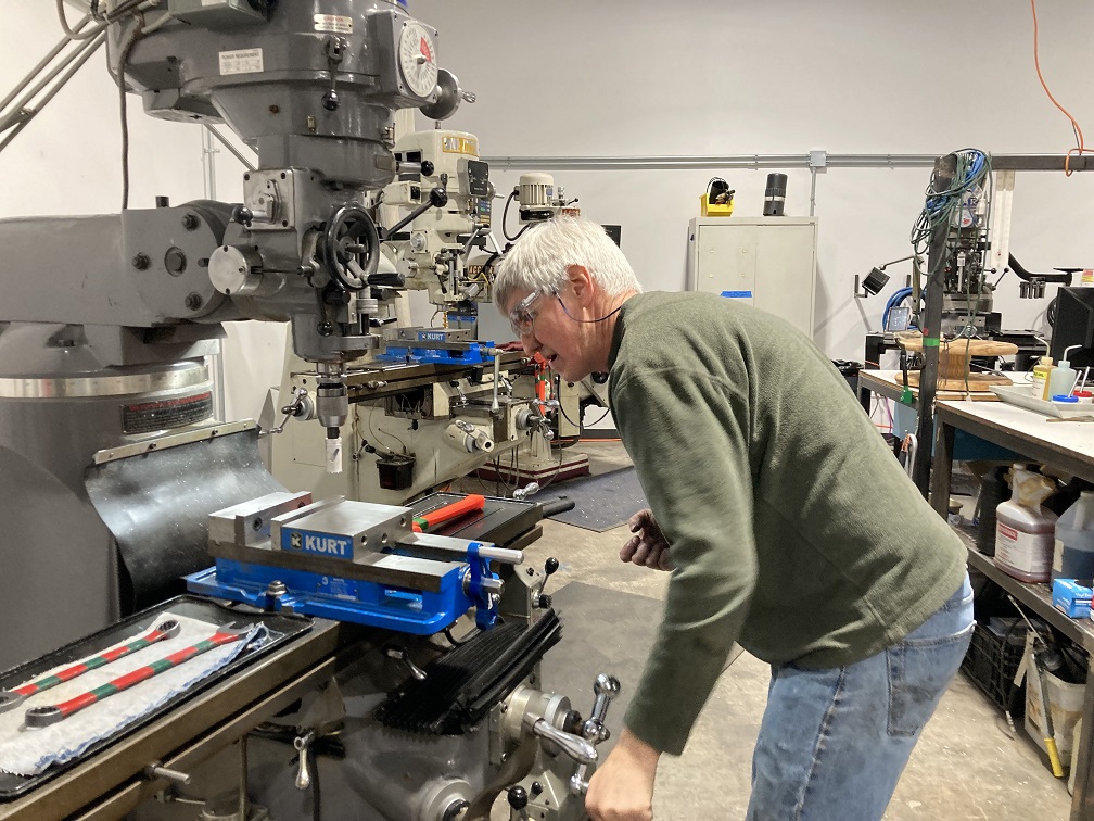
On a milling machine, parts are created by removing material from a solid block (or workpiece) using a variety of spinning cutting tools.
A 3-axis vertical milling machine has a variable-speed vertical spindle and a heavy table that translates underneath it. A metal workpiece is clamped to the table and a cutting tool is held in the spindle. Cutting is done by moving the workpiece against the spinning tool, or by lowering the spinning tool into the workpiece.
A CNC milling machine operates by computer control. Motors are attached to the movement mechanics allowing the computer to make precision-machined parts automatically.
| |
|---|---|
| Use For | Do Not Use For |
|---|---|
|
|
Safety Notes
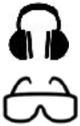
| Eye protection required! | ||
|---|---|---|
Personal
- Wear safety goggles. Eyeglasses are NOT safety goggles.
| |
|---|---|
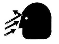
- Beware of flying chips. They are HOT and SHARP.
- Do not wear loose clothing or jewelry when operating the machine. Long hair must be tied back or covered.
- Do not wear gloves. Gloves can be drawn into a cut by the spinning tool.
- Do not remove chips from the cutting area with bare hands. Use a chip brush or a shop-vac.
- Always keep a secure, stable stance. Avoid over-reaching. Clean up oil spills immediately and avoid slipping. Keep the work area clear of trip hazards.
Machine
- Work must be clamped securely in a vise and the vise clamped tightly to the table, or, work must be clamped securely to the table.
- Always stay at the machine while it is running.
- Do not operate the machine if any unusual or excessive heat, noise, smoke, or vibration occurs.
- Make sure the spindle has come to a complete stop before changing tools or unloading the workpiece. Keep hands clear of the spindle start switch when changing tools.
- NEVER USE COMPRESSED AIR to remove chips from the work area.
- Remove all wrenches, chuck keys, and loose parts before turning on the machine.
- Before running machine the spindle should be rotated by hand to make sure it is clear for cutting.
- Make sure the cutter is rotating in the proper direction before cutting material.
- Always use sharp cutters that are in good condition.
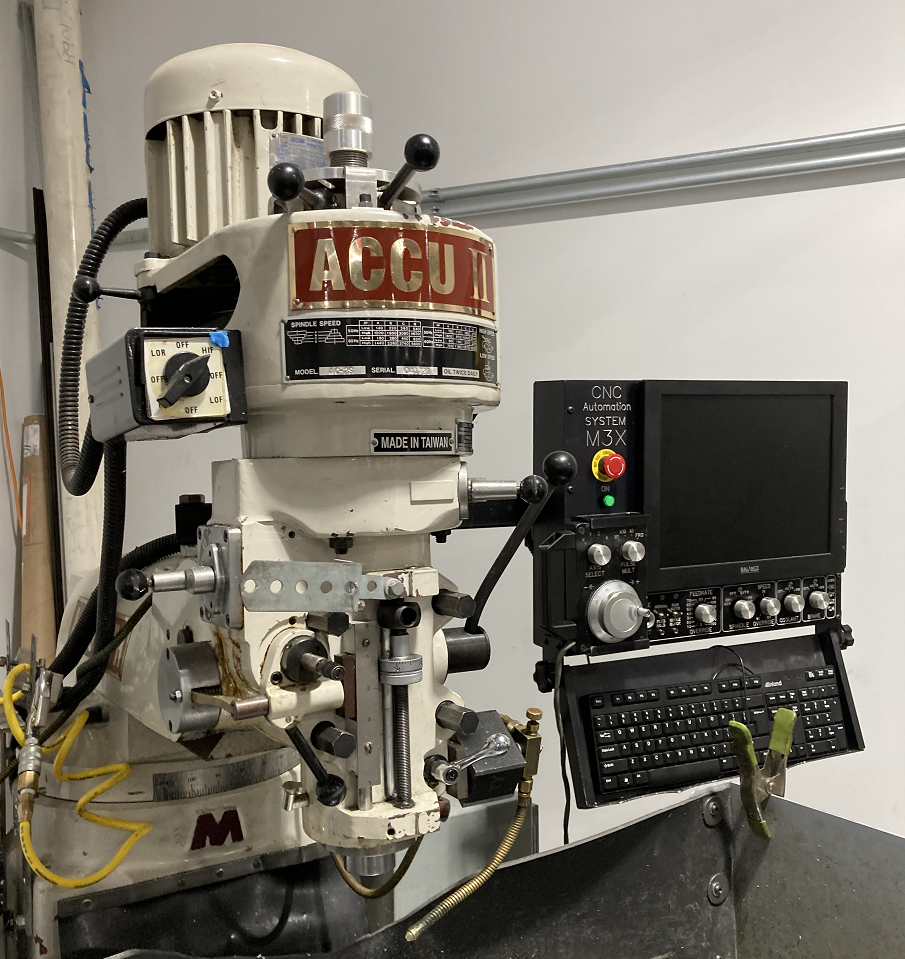
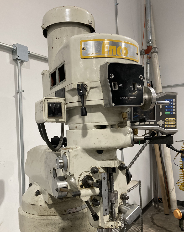
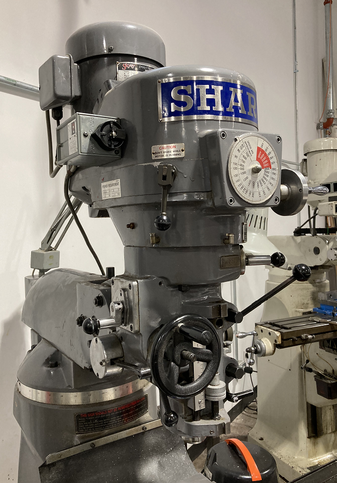
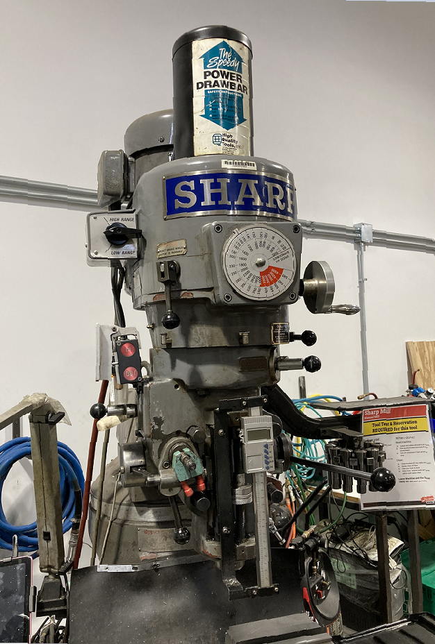
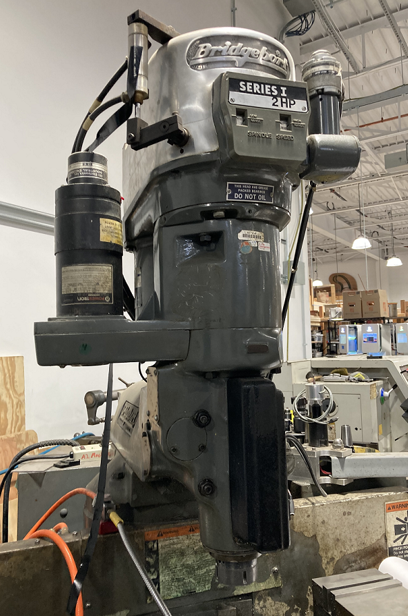
| Accu II Mill | Enco Mill | Sharp Mill "Click" | Sharp Mill "Clack" | Bridgeport Mill |
|---|---|---|---|---|
| CNC | Manual | Manual | Manual | Manual (Out of Service) |
 |
 |
 |
 |
|
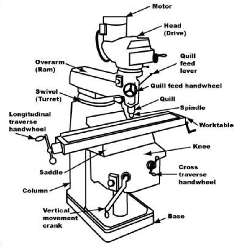
Parts of a Milling Machine
| |
|---|---|
| Parts of a Milling Machine |
Headstock:
The spindle is driven by the motor at the top. Frequently there is a crank-operated speed control located on the front.
An emergency stop (E-STOP) button is always located next the the motor power switch.
The spindle is raised and lowered through the Quill, actuated by a handle on the side of the headstock.
Tools are held in place with a drawbar that extends through the center of the spindle. The draw-bar can be tightened manually or with a pneumatic motor.
Table:
The moving table is carried on the machine's saddle.
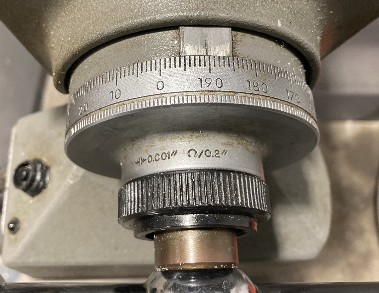
Side-to-side (Longitudinal) motion of the table is controlled by ball crank handles on either end of the table. The scales are incremented by 0.001 inches.
Knee:
In-and-out (Cross) motion of the table is controlled by a crank on the front of the knee, also incremented by 0.001 inches.
The table is raised and lowered vertically by a crank on the side of the knee.
Base and Turret
These provide stability and allow some adjustment of the headstock.
Machine Motion
The X-Y motion of the table and the vertical motions of the knee and the spidle are all actuated by gears and screws, which turn rotary motion into linear motion. Different machines have different means for effecting this motion.
Manual Actuation
| |
|---|---|
| The scale is graduated in "mils" or 1/1000ths of an inch. |
| |
|---|---|
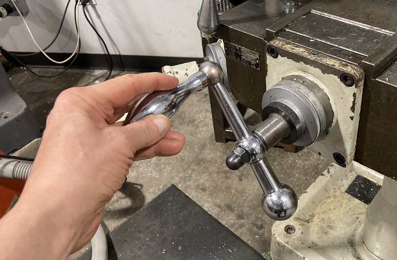
| Hand-cranking the cross-feed on the Enco mill. |
On a manual machine, the motion is created by turning the mechanical input with a crank or a handle. On the table cranks, an "ACME" screw creates a movement of 0.2 inches per rotation.
With this motion, the user must account for the backlash of the screw and the nut riding on it. On a typical mill, this backlash can be approximately 1/20 rotation, or about 0.01 inches in distance.
Mechanization
| |
|---|---|
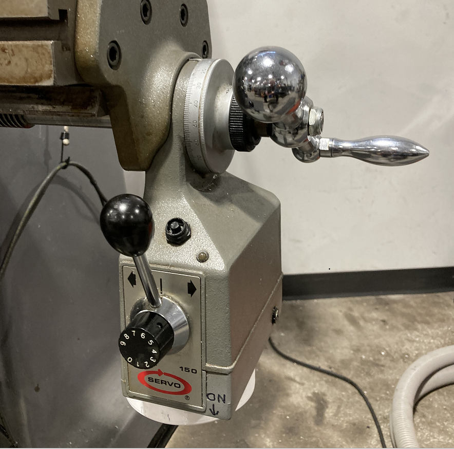
| An add-on motor drive on the Enco mill. |
On some machines, an electric motor is attached to one or more axes of motion. This permits the user to set a uniform speed for milling off a flat surface with an even linear movement.
A clutch handle engages the motor to the hand-crank for motion in either direction. A variable speed control adjusts the rate of motion.
On many machines, the spindle on the headstock has a mechanized vertical movement geared into the spindle rotation, for drilling holes
Computer Numerical Control
| |
|---|---|
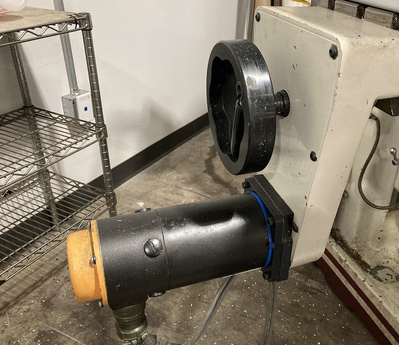
| A servo motor on the Accupath CNC mill. |
On a CNC mill, there is a similar motor drive, but the motor is a DC servo motor that operates under computer control.
A servo motor consists of a DC motor and an encoder, which provides feedback to the computer as to the motor's position.
The optional hand-crank is rarely used, and can only be handled when the servo motor is off.
Pages in category "Milling Machines"
The following 6 pages are in this category, out of 6 total.
