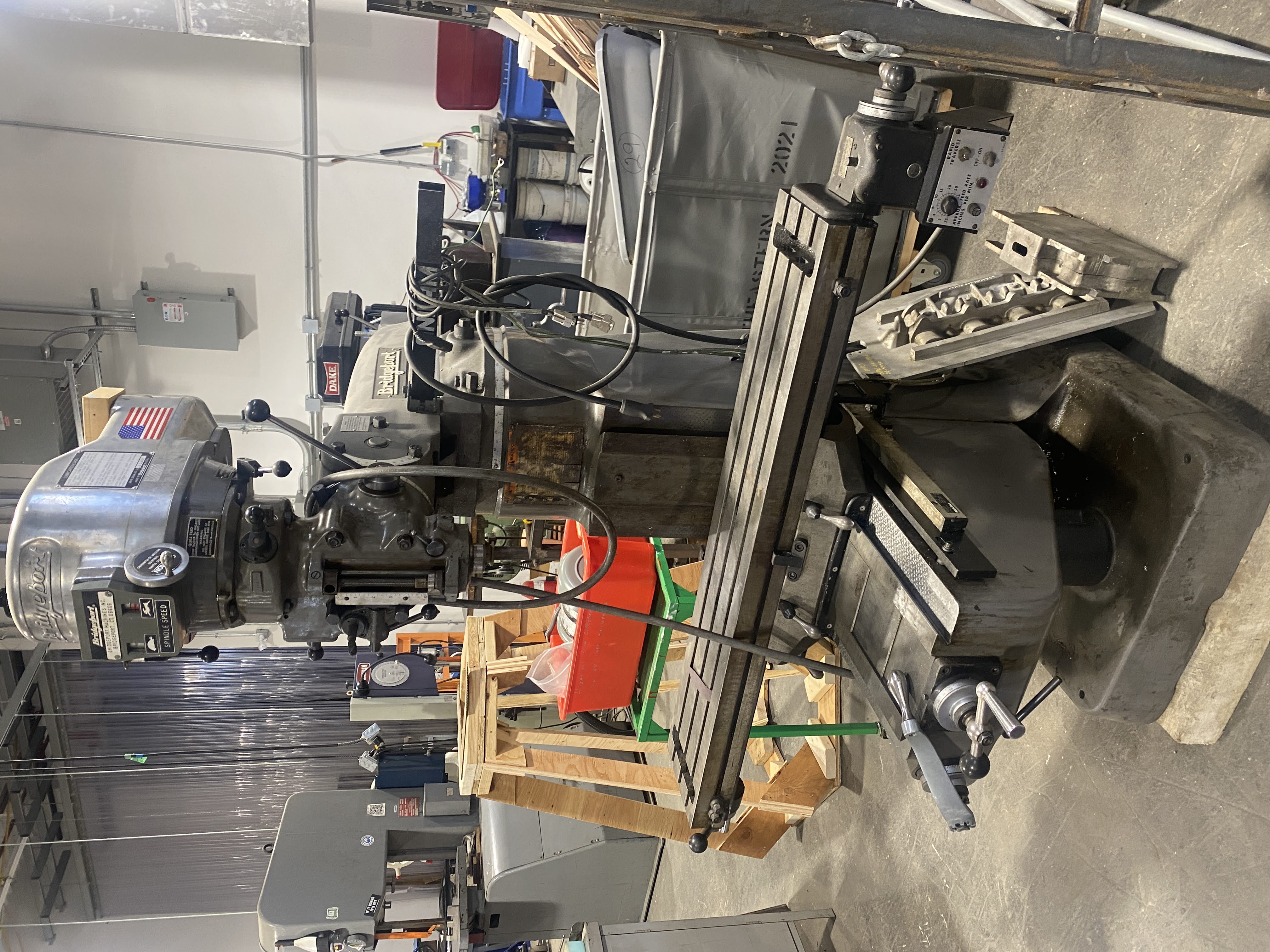
Bridgeport Series 1 Standard Knee Mill
| Bridgeport Series 1 Standard Knee Mill | |
|---|---|
| General Info | |
| Make | Bridgeport |
| Model | Series 1 |
| Serial | J292372 |
| Specs | specs |
| Manual | {{{manual}}} |
| Asylum Info | |
| Location | Machine Shop |
| Rubric | N/A |
| Training | Tool classes |
| Testing | Tool testing |
| Restrictions | red |
See the Milling Machines category for notes on using all 3-Axis Milling Machines
Link to: Machine Shop Main Page
Safety Information
| Eye protection required! | ||
|---|---|---|
Link to: Safety notes on the Milling Machine Category page
Operating Instructions
Textbook: How to Operate a Milling Machine
Calibration
To account for the error caused by inconsistent collet seating in the spindle, it is recommended to check the calibration of the Pro Tram Gage every time it is used. Completing the steps below will position the two indicator tips on a theoretical line that is perpendicular to the spindles axis.
- Install the Pro Tram into spindle.
- Place calibration magnet on the table under one of the indicators.
- Lower spindle until indicator is depressed about 0.100”. Then lock the spindle in place. Be sure to lock the knee of the mill as well.
- Rotate the face of the indicator until the needle reads zero. Then rotate the Pro Tram unit 180 degrees so that the other indicator is contacting the calibration magnet.
- Rotate the face of the second indicator until the needle reads zero.
- After calibration the right and left indicator faces may be rotated to slightly different positions. This is caused by a slight variance in indicator length and will not affect the functionality of the unit.
Operation
- Install the Pro Tram into the spindle. Lock the knee of the mill.
- Position the Pro Tram parallel to the length of the milling machine table. Then lower the spindle until both indicators are depressed by about 0.050”.
- Make adjustments to the head of the milling machine until both indicators read the same number. When this is accomplished the first axis of the milling machine is trammed.
- Position the Pro Tram perpendicular to the length of the milling machine table. Then lower the spindle until both indicators are depressed by about 0.050”.
- Make adjustments to the head of the milling machine until both indicators read the same number. When this is accomplished the second axis of the mill is trammed.
| Caution When installing or removing the Pro Tram from the spindle keep at least one hand on the unit while tightening or loosening the draw bar. This will prevent the unit from accidently falling out of the spindle. If necessary put the machine in low gear to eliminate the need to hold the machine brake lever while tightening or loosening the draw bar. | |
|---|---|
Speed Adjustment

| |
|---|---|
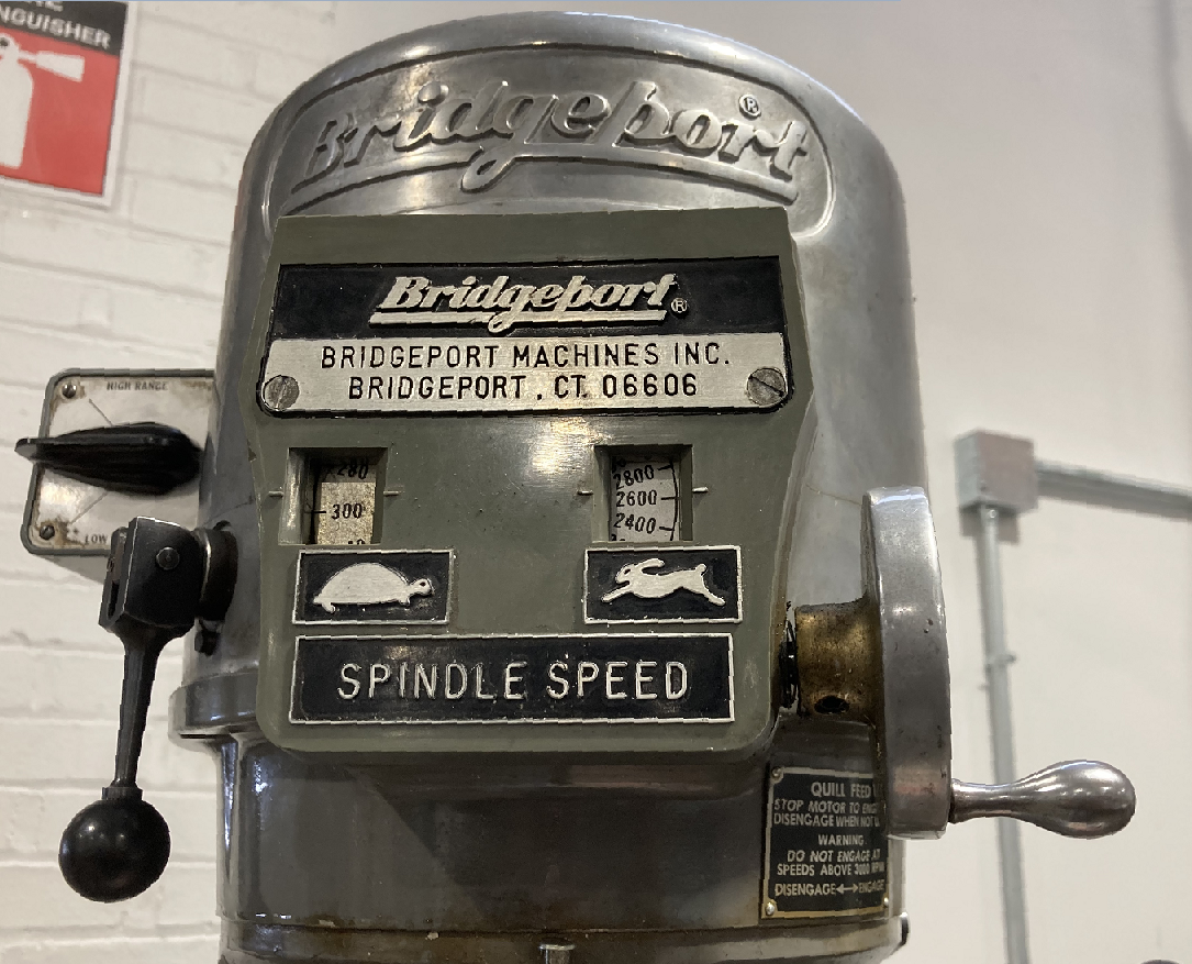
| The speed control on the Bridgeport mill. |
The spindle speed is adjusted manually with the crank on the right-hand face of the headstock. Only adjust the spindle speed when the spindle is turning!
A range-control lever on the left side of the headstock switches between "Tortoise" and "Hare" speed ranges. Change the position of this lever only when the spindle is stopped! The spindle may need to be rotated manually when changing the speed range to allow the gears to mesh. The direction of the spindle reverses between the two modes (note the directions the two animals are facing) and the motor power switch on the left shows the two directions for "forward" rotation in each mode.
This machine has variable-speed motor drives (Not CNC) on the two axes of the table.
Manual Draw-Bar
This machine has manual tool-changing with a wrench.
